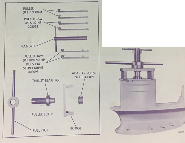
INSTRUCTIONS FOR USE
35 HP AND 40 HP
1. Place the bridge across the gearcase with the hole in the bridge in line with the center of the pinion bearings.
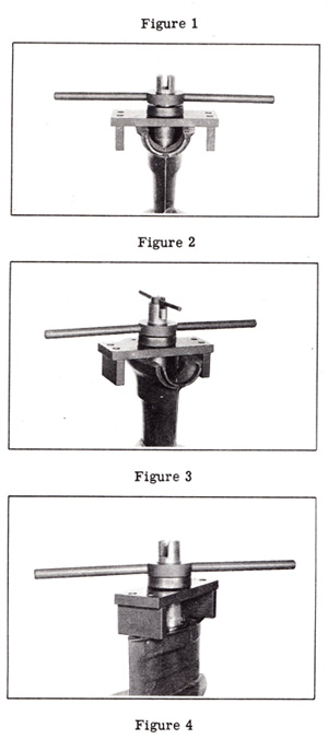
2. Place the thrust bearing on the puller body from the threaded end. Screw the pull nut on to the puller body so the top of the pull nut is approximately 1/4" below the bottom of the slots in the puller body (figure 2). Insert the machined end of the puller body thru the hole in the bridge and seat in the pinion bearing (figure 2).
3. Insert one puller jaw (308093) thru the center of the puller body and hook the notch into the narrow slot in the puller body. Insert the other puller jaw (308093) and hook the notch in the wide slot in the puller body.
4. Insert the mandrel into the puller body, locating the puller jaws in the slots in the mandrel. Push the mandrel down until the cross rod of the mandrel rests on top of the puller jaws (figure 3). Warning:::: Do Not Force mandrel. If any difficulty is encountered in inserting the mandrel, check the positioning of the puller body and puller jaws, as outlined above.
5. Hold cross handle on mandrel to prevent puller body from turning, and turn pull nut clockwise to remove bearings.
50 HP
Before placing the bridge on the gearcase, insert the adapter sleeve (308097) into the lower bearing, and proceed as listed for 40 HP motor, using puller jaws (308094). The adapter sleeve is merely used to prevent the needles from falling out while pulling the bearings.
60 HP AND 75 HP
Place the bridge on the gearcase and proceed as with the 40 HP, using puller jaws (308095). Note: When pulling the bearings on the 60 HP and 75 HP motors, the puller jaws must be lined up fore and aft, as there are side obstructions in the gearcase (figure 4).
When inserting the mandrel which locks the jaws in position, any undue force resisting the insertion of the mandrel indicates the jaws are not properly lined up, the bearings were improperly installed, or the wrong jaws are being used. NEVER FORCE THE MANDREL. |