| Home | Links | Comments | About | Contact |
|---|
Rod Cap Alignment Fixture Aligns connecting rod during torquing procedure |
 |
Instructions
These instructions contain two parts. Part one describes rod assembly procedure using Rod Assembly Fixture. Part two describes procedure to check and adjust torque handle clutch.
The Rod Assembly Fixture will make it very easy to accurately assemble the rod cap to rod. It can be used on the 25 thru V-8 recreational models. The manufacturing procedure of hand-sanding the rod corners was changed to precision grinding so an assembly fixture could be used. The rods with precision-ground corners were used starting with:
• Outboard - during models CO 25 thru 75 & CR V-4 & V-6 and beginning models CO V-4 120 & 140 and V-8.
• OMC Sea Drive - during models CR 1.6, 2.5 and 2.6 Liter.

Actions to be Performed: Part One - Rod Assembly Procedure
Step 1. Prepare for Rod Assembly
Step 2. Review Components of Rod Assembly Fixture
Step 3. Setting Rod Engagement Stop
Step 4. Jaw Installation
Step 5. Rod Cap Assembly
Step 1. Prepare for Rod Assembly
1. Read assembly instructions completely prior to starting work,
2. Determine if the rods you are working with have precision-ground corners.
[1] • A rod with precision-ground corners has grind marks (A) that run across the corner.
[2] • A rod with hand-sanded corners has grind marks (B) that run the length of the corner.
Do not attempt to assemble rods with hand-sanded corners with Rod Assembly Fixture.
3. Obtain Hand Tools:
Torque Wrench, 0-10 N•m (0-75 in. lbs.)
Torque Wrench, 0-101 N•m (0-75 ft. lbs.)
3 in. Extension - 3/8 in. Drive
1/2 in. to 3/8 in. Adapter
Socket - Rod Screw Torquing, P/N 331638
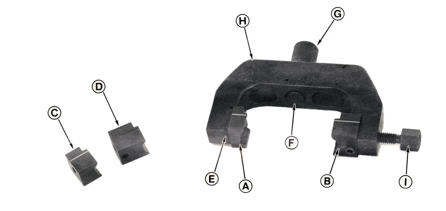
Step 2. Review Components of Rod Assembly Fixture
[3] Rod Assembly Fixture
(A) Restraining Jaw
(B) Forcing Jaw
(C) Restraining Jaw (Narrow)
(D) Forcing Jaw (Narrow)
(E) Molded Bushing
(F) Engagement Stop
(G) Engagement Stop Adjustment Knob
(H) Frame
(I) Forcing Screw
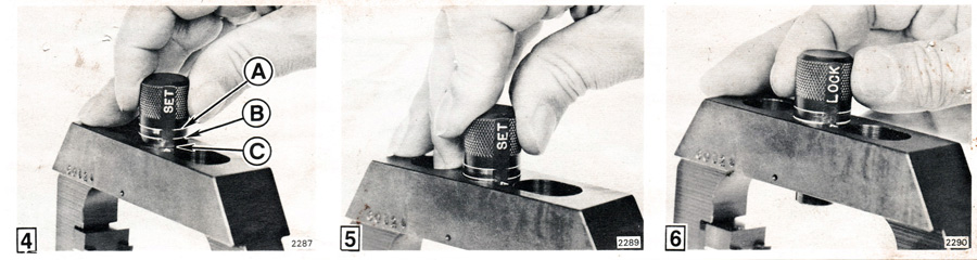
Step 3. Setting Rod Engagement Stop
[4] 1. Align the flat marked "set" on the rod engagement stop adjustment knob to the arrow on the frame. This will allow the adjustment knob to be moved up and down through set range.
[4] [5] 2. Press adjustment knob to desired setting.
Models CO 25 thru 75 (A)
Models CR V-4 & V-6, CO V-4 90 & 115. and V-6 (B)
Models CO V-4 and V-8 (C)
[6] 3. Rotate adjustment knob 180° to the lock position.
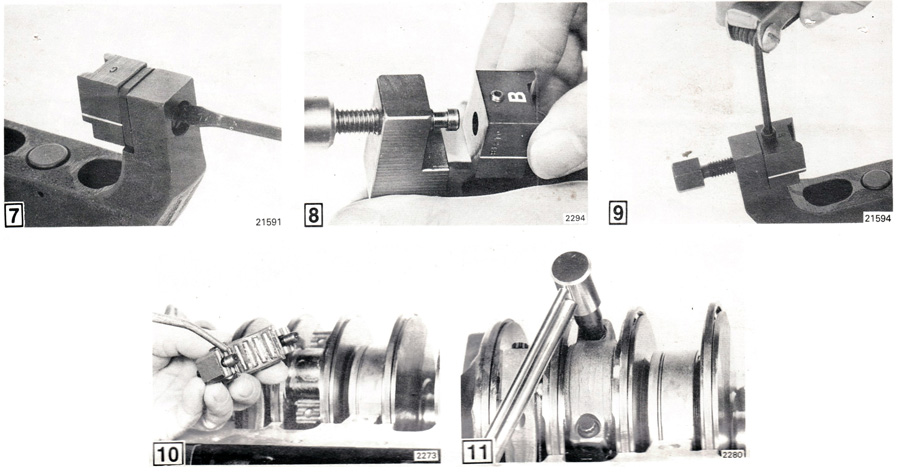
Step 4. Jaw Installation
The Rod Assembly Fixture has two sets of jaws. Each set contains a movable "forcing" jaw and a fixed "restraining" jaw. The forcing jaw is held onto the forcing screw by a screw and the restraining jaw slides into a molded bushing in the frame.
The jaws are identified by the letters A. B. C & D.
Models CO V-4 120 & 140, and V-8 use restraining jaw "A" and forcing jaw "B."
Models CR V-4 & V-6, CO 25 thru 75, V-4 90 & 115, and V-6 use restraining jaw "C" and forcing jaw "D."
[7] 1. Place restraining jaw against bushing with identification letter facing away from frame. Screw restraining jaw into place.
[8] 2. Place forcing jaw onto forcing screw.
[9] 3. Tighten screw securing jaw.
Step 5. Rod Cap Assembly
Starting with the rods and bearings positioned to crankshaft for assembly:
[10] 1. Apply outboard oil to rod screws and assemble rod cap to rod.
[11] 2. Tighten rod screws to a torque of 2-3 N•m (25-30 in. lbs.).
3. Apply a light coat of outboard oil to the corners of rod.

4. Place assembly fixture on connecting rod using the following procedure
[12] • Position fixture onto rod so the contact area (K) of the jaw is centered on the side of the rod (L).
• Tighten forcing screw until jaws contact rod.
[13] • Slide fixture onto rod until the rod engagement stop contacts rod (M). The grooved lines on the jaws must center on the rod/crankpin diameter.
[NOTE] The above procedure must be followed to assure fixture is squarely in position.
[14] 5. Tighten forcing screw to a torque of 23 in. lbs. (2,5 N•m).
6. Loosen both rod screws 1 /4 turn. This allows the tool to align the rod cap to the rod.
[15] 7. Apply a preliminary torque of 5-7 N•m (40-60 in. lbs.) to both rod screws. This prevents the rod cap from skewing when full torque is applied.
8. Apply final torque in two alternate increments to both rod screws.
Final Torque:
• 25 thru V-6 except CO V-4 120 & 140 - 40-43 N•m (30-32 ft. lbs.)
• CO V-4 120 & 140 and CO V-8 57-60 N•m (42-44 ft.lbs.)
9. Loosen force screw and remove assembly fixture.