Johnson Service Bulletin SB-1006 - Steering Handle Shaft and Rack Alignment
Issued February 26, 1964, this bulletin gives two procedures for aligning the steering handle shaft with the rack and link assembly on Johnson 9½ H.P. outboards. Factory drawings show the first-tooth alignment and armature-plate linkage.

February 26, 1964
SUBJECT: INSTRUCTIONS FOR ALIGNING STEERING HANDLE SHAFT WITH RACK AND LINK ASSEMBLY - 9½ HP ENGINES.
A. When only steering handle shaft has been removed.
- Remove both spark leads as a safety precaution to prevent the engine from accidentally starting.
- Reach underneath flywheel and turn armature plate clockwise - as far as it will go. So doing automatically moves rack to maximum slow speed limit.
- Assemble bow washer over short end of steering handle shaft and insert short end of shaft into steering handle bushing - aligning first tooth of gear with first notch in rack. See drawing #1 on reverse side.
- Assemble plain washer and retaining ring to short end of shaft from back side of steering handle. Use No. 2 TRU-ARC PLIER to install retaining ring.
- Assemble twist grip to steering handle shaft so that red indicator dot is positioned near word "stop". Install and tighten twist grip retaining screw.
- Turn twist grip back and forth between "stop" and "fast" positions several times. If the rack & gear have been aligned according to instructions they will stay in mesh. Should the rack and gear run out of mesh at the "fast" end of twist grip travel, re-alignment according to instructions is necessary.
NOTE: Red indicator dot on twist grip handle will usually travel slightly beyond "stop" and "fast" positions when the gear and rack are properly meshed.
- Secure spark plug leads.
B. When both steering handle and rack have been removed.
- Remove both spark plug leads as a safety precaution.
- Slide rack into steering handle and connect linkages as shown in drawing #2 on reverse side.
- Proceed with steps one through seven as outlined above for steering handle shaft assembly.
Service Department
NOTE: Post on your MQ-9½ HP index under the heading "Lower Unit".
JOHNSON MOTORS, DIVISION OF OUTBOARD MARINE CORPORATION, WAUKEGAN, ILLINOIS 60086SERVICE BULLETIN SB-#1006
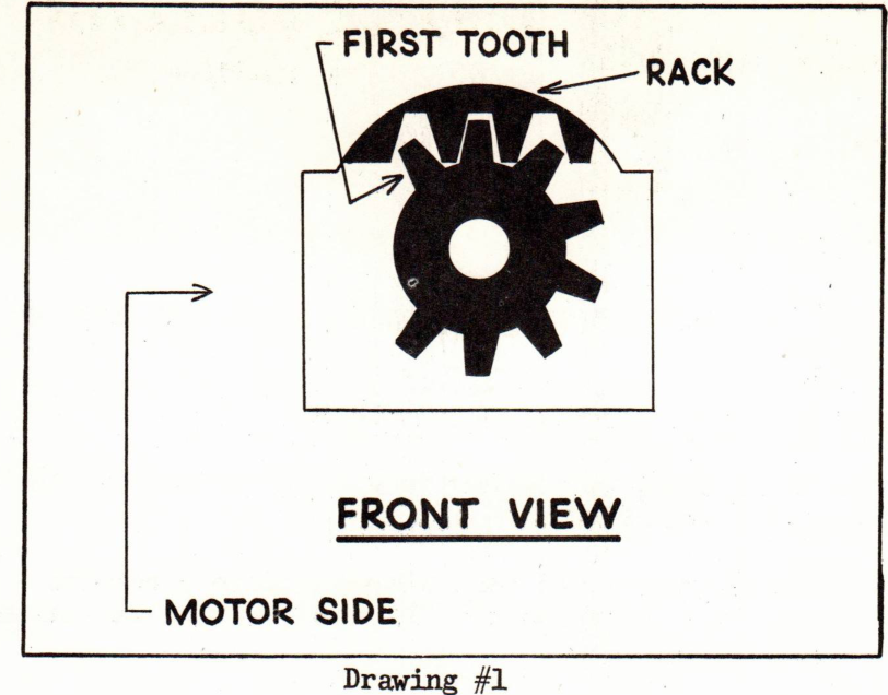
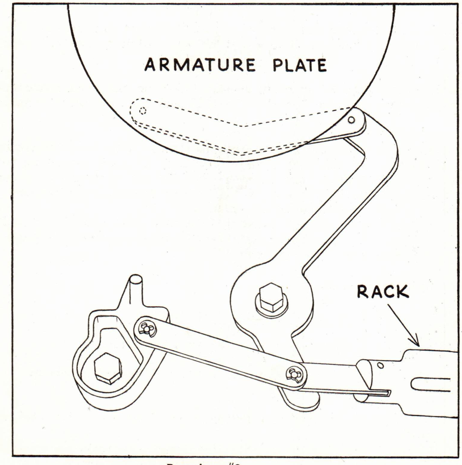
SB-1006 describes the steering handle shaft and rack alignment for Johnson 9½ H.P. engines. Drawing #1 illustrates gear engagement at the first tooth; Drawing #2 identifies the rack and armature-plate linkage.