1960s Service Bulletins / SB-1049

Johnson Service Bulletin SB-1049 - Engine Cable to Junction Box Connection

Issued April 1965, this bulletin explains the correct routing and connection of battery, ground, and starter cables inside the junction box on 1964 and 1965 40, 60, and 75 H.P. DC-generator-equipped engines. It includes a ground-terminal comparison diagram and four factory installation photographs.

Johnson Motors Service Bulletin letterhead

April, 1965

SUBJECT:   ENGINE CABLE TO JUNCTION BOX CONNECTION

ON ENGINES:  1964 AND 1965 40, 60 AND 75 H.P. ENGINES EQUIPPED
              WITH DC GENERATORS.

The following recommended procedure for connecting the engine cable assembly of 40, 60 or 75 H.P. engines equipped with DC Generators, to the appropriate terminals in the junction box, has been found to facilitate installation of the junction box cover:
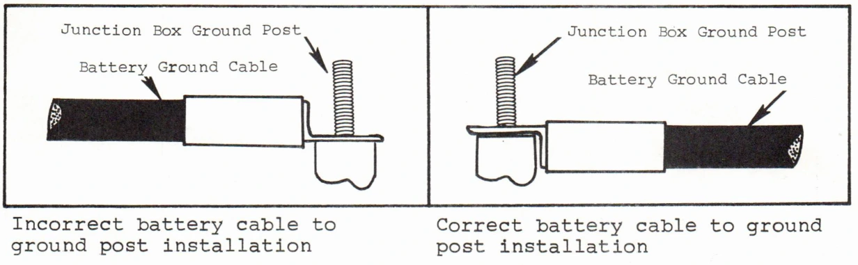
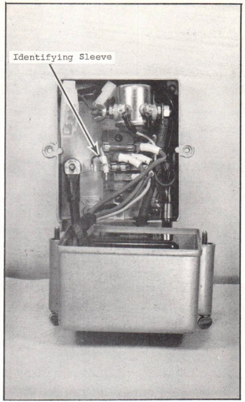
A.Connect the black ground cable from the battery to the ground post as shown in Figure 1 and in the manner illustrated below.
Incorrect and correct battery cable to ground post installation
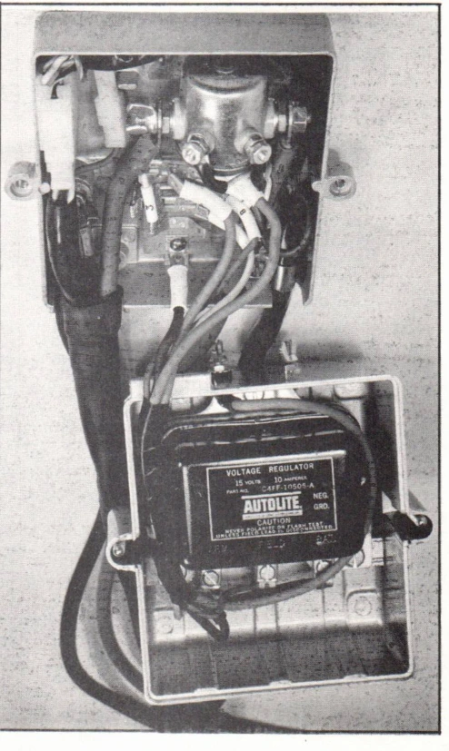
B.Install the black engine ground cable and the wing nut over the battery ground cable, on the Ground Post, as shown in Figure 3.
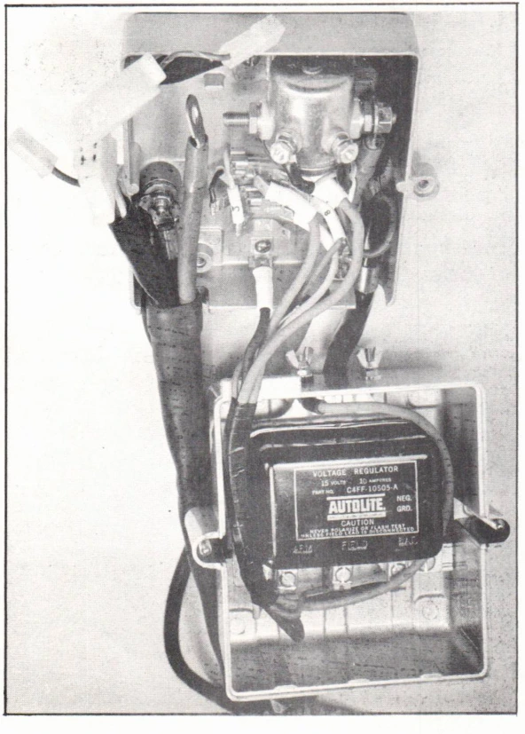
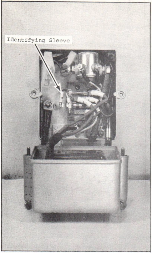
C.Slide the white identifying sleeve (with the Number 4 on it) back along the blue wire until the sleeve is under the terminal strip. (Figure 2)
D.Tuck the blue wire out of the way, as much as possible, so as to provide as much room as possible for the red starter cable from the engine.
E.Neatly tuck the regulator harness along side the regulator as shown in Figure 3.
SERVICE BULLETIN SB-#1049
JOHNSON MOTORS, DIVISION OF OUTBOARD MARINE CORPORATION, WAUKEGAN, ILLINOIS 60086
Figure 1
Figure 1
Figure 2
Figure 2
Figure 3
Figure 3
Figure 4
Figure 4
SERVICE BULLETIN SB-#1049
JOHNSON MOTORS, DIVISION OF OUTBOARD MARINE CORPORATION, WAUKEGAN, ILLINOIS 60086
F.Connect the red starter cable to the solenoid being sure that this cable is as close to the back of the junction box as possible, so that it will clear the regulator.
G.Position the large plastic connector on edge, placing the small connector (when used) along side of it, as shown in Figure 4.
H.Install junction box cover.
JOHNSON MOTORS

N. Peter Hansen
Administrative Assistant

NPH:rs

NOTE:   Post on your RD, and RK 40 H.P. Indexes, your VX 60 H.P. Index, and your V4, 50 and 75 H.P. Indexes under "Electrical."