
May, 1965
SUBJECT: GEARCASE REMOVAL - CD-22M
ON ENGINES: 1965 CD-22M ENGINE
Please be advised that it is not necessary to remove the powerhead of the subject engine when it is desired to remove the gearcase from it. A procedure for gearcase removal and installation for the subject engine is enclosed and if followed, will be found to greatly facilitate these operations.
I. Gearcase Removal - CD-22M
A. Remove both spark plugs and GROUND EACH OF THE HIGH TENSION LEADS!
B. Remove the four (4) - 7/16" hex-head cap screws that secure the gearcase to the exhaust housing.
C. Apply a slight amount of downward pressure to the gearcase while slowly turning the flywheel in the direction of engine rotation.
────── CAUTION ──────
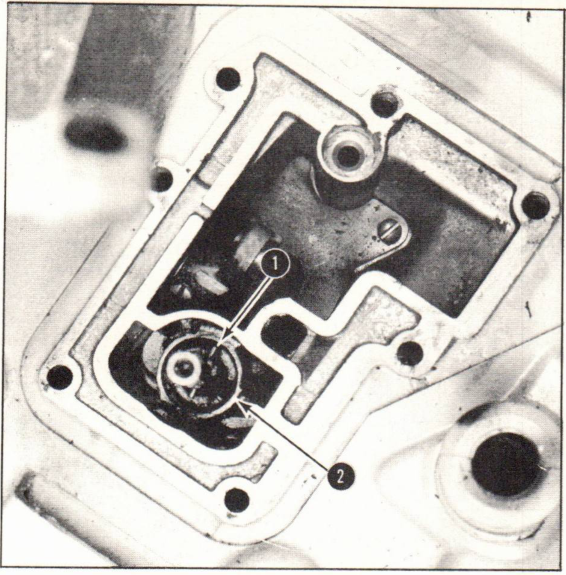
Only a reasonable amount of pressure should be used in performing step "C", since excessive pressure will tend to bend the Driveshaft Pin, Part Number 303261, that is in the top of the driveshaft. (See Arrow "1" in Figure 1.)
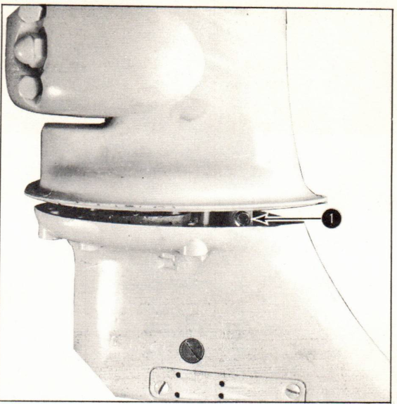
You will note that the reason for rotating the flywheel is so that the 303261 Driveshaft Pin will line up with the slot in the Driveshaft Casing (see Arrow "2" in Figure 1). Once the Driveshaft Pin lines up with this slot, the top surface of the gearcase will drop far enough below the bottom surface of the exhaust housing, provided that the shift lever is in full Reverse position, so that the 3/8" hex-head cap screw that holds the lower shift rod in the shift rod connector can be removed. (See Arrow "1" in Figure 2.)
Once the lower bolt in the shift rod connector is removed, there is nothing to keep the gearcase from dropping out of the exhaust housing. Therefore, care should be exercised during gearcase removal so as to avoid damage to the gearcase, caused by inadvertently allowing it to strike the shop floor.
II. Gearcase Installation - CD-22M
Installation of the CD-22M gearcase is practically the reverse operation from removing it. The following suggestions, however, will be found to facilitate installation:
A. Insert the driveshaft of the assembled gearcase into the driveshaft casing of the exhaust housing.
B. Make certain that the water tube gets started properly into the grommet in the water pump housing.
────── Note ──────
A light coating of a Studebaker Corporation product called S.T.P., when applied to the water tube, just prior to its being inserted into the grommet in the water pump housing, is recommended and will be found to be a valuable aid during gearcase installation.
C. With the shift lever in full Forward position, continue sliding the gearcase toward the exhaust housing, until there is approximately a one (1) inch space between the upper surface of the gearcase and the lower surface of the exhaust housing.
D. While holding the gearcase in the position described in step "C", slowly move the shift lever toward the reverse position so that the lower shift rod begins to engage the shift rod connector.
E. When the bolt hole in the shift rod connector is lined up with the groove in the lower shift rod, install the 3/8" hex-head shift rod connector bolt and lock washer and tighten only until the two halves of the connector come together.
F. If it is found that the gearcase can not be brought up flush with the exhaust housing, turn the flywheel in the direction of engine rotation and at the same time gently squeeze the exhaust housing and gearcase together. A definite bump will be felt when the driveshaft pin lines up and goes through the slot in the driveshaft casing and the splines on the driveshaft engage the splines in the crankshaft. (During this operation, it is assumed that the spark plugs are removed and the high tension leads are still grounded.)
G. Moving the shift lever to the forward position while pushing the gearcase toward the exhaust housing, will allow the top surface of the gearcase to fit flush against the bottom surface of the exhaust housing.
H. Installation and torquing of the four (4) - 7/16" hex-head cap screws that secure the gearcase to the exhaust housing will complete this installation. The recommended torque to be applied to these screws is from 5 - 7 foot pounds!* (Torque Specification for all Johnson Outboard Motors are available by referring to SB-#901 Rev. 1.)
*Note: Torque wrenches calibrated in inch pounds are more accurate than those calibrated in foot pounds. Foot pound torque specifications should be multiplied by twelve (12) for use with torque wrenches calibrated in inch pounds.
N. Peter Hansen
Administrative Assistant
NPH:rs
NOTE: Post on your CD-6 HP Index under the heading "Lower Unit."