
SUBJECT: VOLTAGE REGULATORS NO. 377001 AND 380250
MODELS: 1964-1965 28 THRU 75 HP ENGINES EQUIPPED WITH D.C.
GENERATOR AND RADIO NOISE SUPPRESSION KITS.
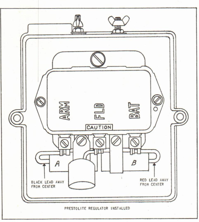
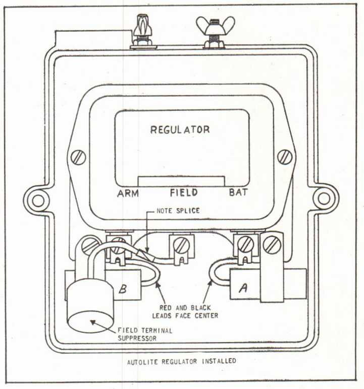
It will be noted that two regulators, namely the No. 377001 (Prestolite No. VBO-4201Y-1) and the No. 380250 (Autolite No. C4FF-10505A), are used interchangeably on the above models. Although these two regulators are completely interchangeable in all applications, a certain amount of confusion has arisen when a Prestolite regulator is replaced by an Autolite regulator on an engine equipped with a Radio Noise Suppression Kit. The problem arises because the mounting tabs of the Autolite regulator are spaced wider and must be secured to the alternate mounting holes of the junction box. When this is done, the mounting position of the condensers and suppressor must be changed as follows:
1. The regulator armature and accessory terminal condenser, which has a black lead (Letter A - Figures 1 & 2), and the regulator battery terminal condenser, which has a red lead (Letter B - Figures 1 & 2), are mounted at the regulator hold-down screws. These condensers should be moved to the relocated regulator mounting screws.
(over)
JOHNSON MOTORS, DIVISION OF OUTBOARD MARINE CORPORATION, WAUKEGAN, ILLINOIS 60085
Note that the condensers are switched, side for side, so that the leads face toward rather than away from each other. The condensers must be switched from side to side, rather than just inverted, to relocate the leads. Simply inverting the condensers results in an interference fit within the junction box.
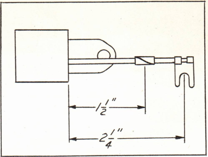
2. The regulator field terminal suppressor should also be re-mounted as shown in Figure 2. Before mounting, however, the suppressor lead should be measured and compared to Figure 3. If the lead is of the shorter length, it must be lengthened approximately 3/4" by splicing in a piece of 18 gauge wire.
JOHNSON MOTORS
N. Peter Hansen
Administrative Assistant
NOTE: Post on your RD, RK, VX 60 HP, and V4 75 HP Indexes under the heading of "Electrical."
NPH:rs