
Johnson Service Bulletin SB-1076 - Torque Tension Chart for 1966 Engines

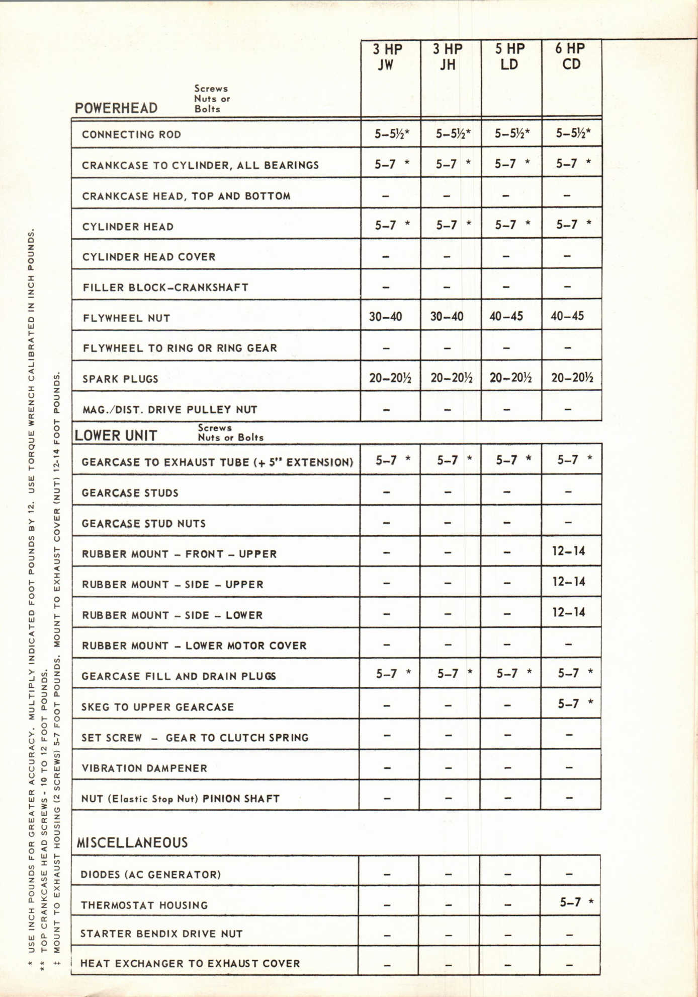
Issued November 1965, this bulletin explains correct fastener tightening and provides factory torque charts for 1966 Johnson outboard engines. The dense factory specification charts are reproduced as scanned images to preserve their exact values and footnotes.

Johnson Motors Service Bulletin header

November, 1965

SUBJECT: Torque Tension Chart for 1966 Engines . . . Screws, Nuts and Bolts (Refer to Service Manual for Torque Tensions on Engines prior to 1966.)

Proper torque tension on screws, nuts and bolts is extremely important when servicing Johnson outboard engines. Over-torquing can warp castings and create a friction bind or a water leak in an engine. Over-torquing may also result in stripped threads which increases labor costs when having to drill, re-tap and install a heli-coil.

Screws left loose are apt to back out. Internally, such screws will cause extensive damage to the powerhead and/or gearcase. Externally, loose screws invite leakage at gaskets or between crankcase halves, etc.

Needless to say, the only certain and recommended method of properly tightening screws is by using a torque wrench. These wrenches are readily available and may be purchased at reasonable costs from local parts houses, tool jobbers and mail order houses. They will rapidly pay for themselves in expert workmanship.

TORQUE SEQUENCE
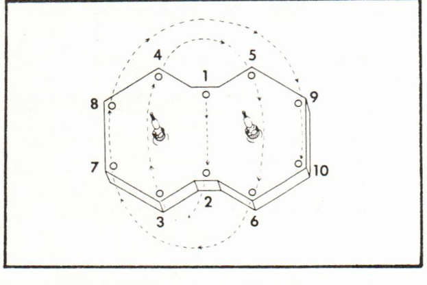
Original numbered torque tightening sequence

When torquing surfaces such as cylinder heads, exhaust covers, intake manifolds, etc., always follow the recommended sequence illustrated in Figure 1. Start at the middle and work evenly towards each end in a circular motion.
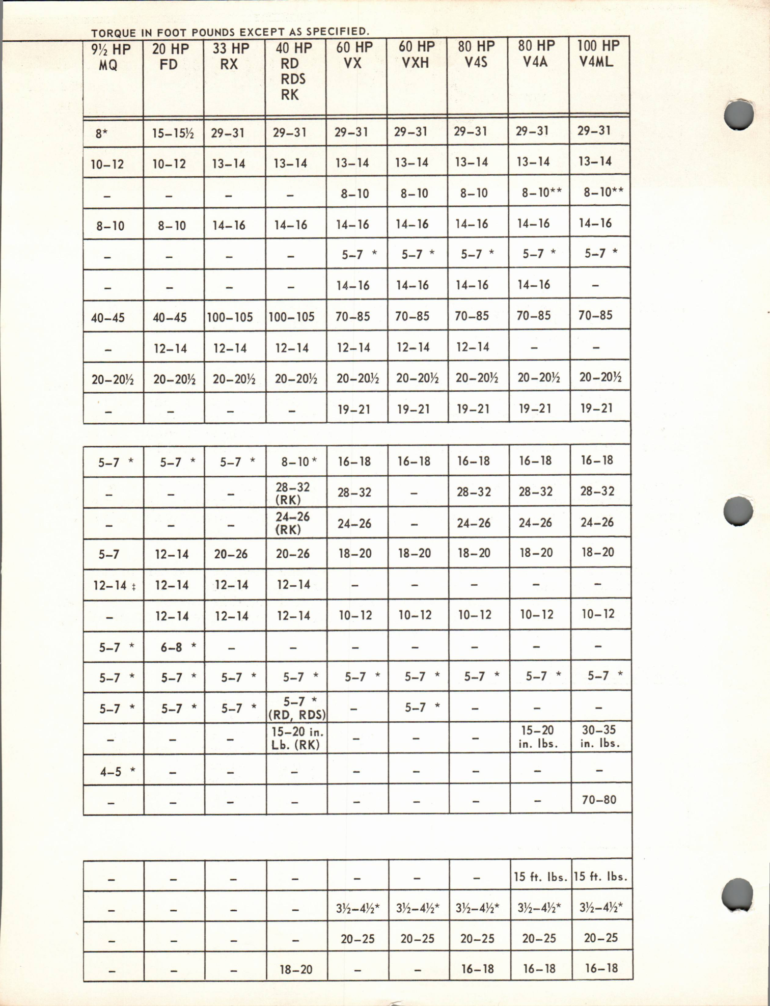
Original factory torque specification chart, scan page 2
Original factory torque specification chart, scan page 3
PAGE 2      SERVICE BULLETIN SB-#1076
JOHNSON MOTORS, DIVISION OF OUTBOARD MARINE CORPORATION, WAUKEGAN, ILLINOIS 60086

GENERAL TORQUE VALUES
These apply to all engines unless otherwise specified under the individual engine specifications contained on the reverse side.

SCREW SIZE:FT. LBS.INCH LBS.
#6 (32 & 40 thds/inch)-7-10
#10 (24 & 32 thds/inch)2-324-36
#12 (24 & 28 thds/inch)3-436-48
1/4" (20 & 28 thds/inch)5-760-84
5/16" (18 & 24 thds/inch)10-12120-144
3/8" (16 & 24 thds/inch)18-20216-240
Spark Plugs (all models)20-20½240-246

JOHNSON MOTORS
N. Peter Hansen
Administrative Assistant

NPH:rs

Searchable reference: engine models and torque chart subjects

The following engine models and component categories appear in the original factory torque charts. They are provided for search and identification; consult the original scanned charts above for exact model-specific torque values and notes.

1966 engine models

Components and fasteners

Note: This bulletin is a torque specification guide, not a numbered replacement-parts catalog. No replacement part numbers are listed in these charts.