Johnson Service Bulletin SB-1081 - Spring Type Propeller Nut Retainer
Issued January 1965, this three-page factory bulletin describes inspection and correction of the spring type propeller nut retainer, part 311766, used with propeller nut 380610. The five factory illustrations show the required retainer shape and the adjustment procedure.

January, 1965
SUBJECT: 311766 SPRING TYPE PROPELLER NUT RETAINER
ON MODELS: VX-11, V4S-17 THRU, V4A-17 THRU, V4M-11C
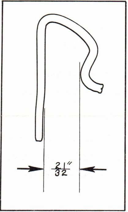
There is a very strong possibility that there are many of the subject retainers in the field that are improperly formed. The shape of this retainer is critical since it is its shape that provides it with the spring lock type of action that holds it in the 380610 Propeller Nut, which, in turn, secures the propeller to the propeller shaft.
If the opening in the retainer should happen to be too wide, it is conceivable that the retainer could fall out during operation of the engine - resulting in the loss of the retainer, prop nut, drive pin, thrust washer and propeller.
JOHNSON MOTORS, DIVISION OF OUTBOARD MARINE CORPORATION, WAUKEGAN, ILLINOIS 60086
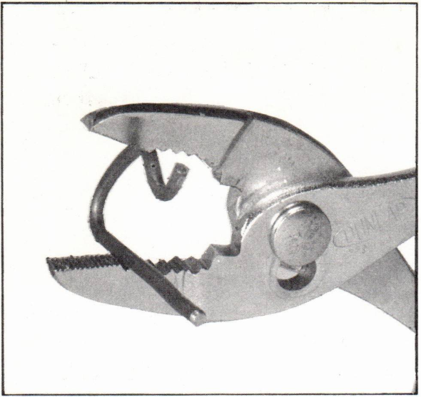
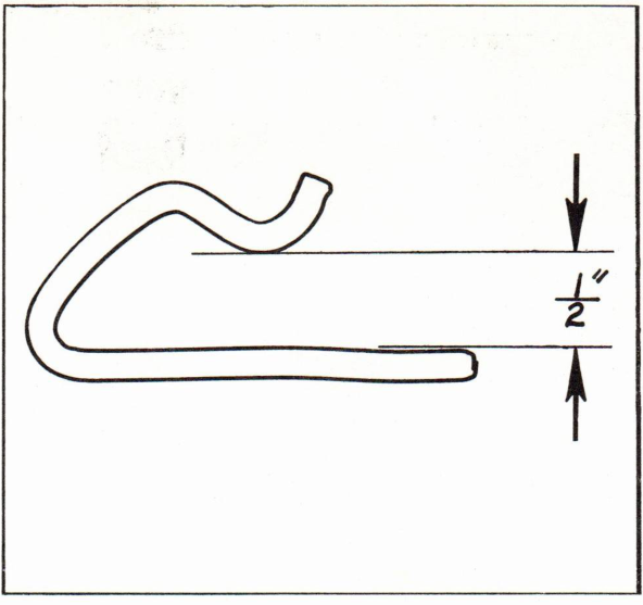
The following procedure should be followed in the event that you happen to have any misformed retainers in stock or find them on engines that come into your shop for service:
1. Place any suspect retainer over figure one (1) of this bulletin and check to see that the legs of the retainer fall within the black outline. If they do, the retainer is properly formed; if they do not, proceed with steps 2 and 3.
2. Grip the retainer with a pair of pliers as shown in figure two (2) and squeeze the legs of the retainer together such that when the pliers are removed, the legs are 1/2" apart. The distance between the legs can be measured with a scale or the retainer can be placed over figure three (3) to see if they fall within the outline. Repeat this step until the 1/2" dimension is attained.
JOHNSON MOTORS, DIVISION OF OUTBOARD MARINE CORPORATION, WAUKEGAN, ILLINOIS 60086
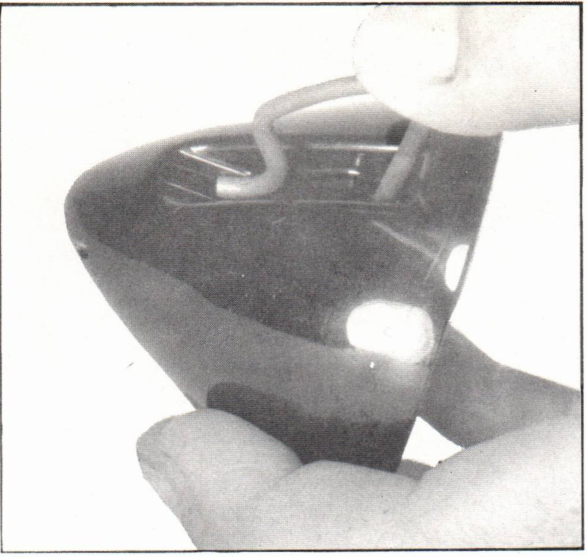
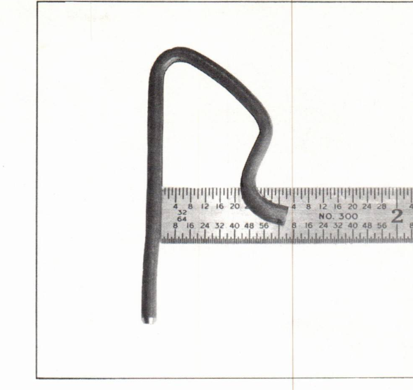
3. Next, fully insert the retainer in a 380610 Propeller Nut. (Figure 4.) This may prove to be slightly difficult the first time that it is done, but once the retainer is installed and then removed, it will be found to have assumed its proper shape with its legs spread from 5/8" to 21/32" apart. This dimension can be checked with the aid of a small scale (figure 5), or by placing the retainer on figure one (1) - checking to see that the retainer falls within the outline shown. Repeat this procedure as required until a 5/8" to 21/32" dimension between the legs of the retainer is attained.
On subsequent installations of the retainer in the 380610 Propeller Nut, it should seat into the nut with a "snap".
N. Peter Hansen
Administrative Assistant
NOTE: Post on your VX-60 HP, V4-75 HP and V4M-90 HP Indexes under the heading "Lower Unit".
Historical parts reference
This bulletin identifies spring type propeller nut retainer 311766 and propeller nut 380610. Figures 1-5 are reproduced from the factory scan. Measurements in the illustrations are historical factory references and should not be taken from a browser display at physical scale.