Johnson Service Bulletin SB-1096
June 10, 1966 - Extending the Switch Cable Assembly. Factory instructions for extending the switch cable on V4A-17 through 18 and V4M(L)-11 through 12 engines. Pages 1-2 are searchable text; pages 3-4 preserve the original six factory photographs.

June 10, 1966
SUBJECT: EXTENDING THE SWITCH CABLE ASSEMBLY
ON MODELS: V4A-17 THRU 18 and V4M(L)-11 THRU 12
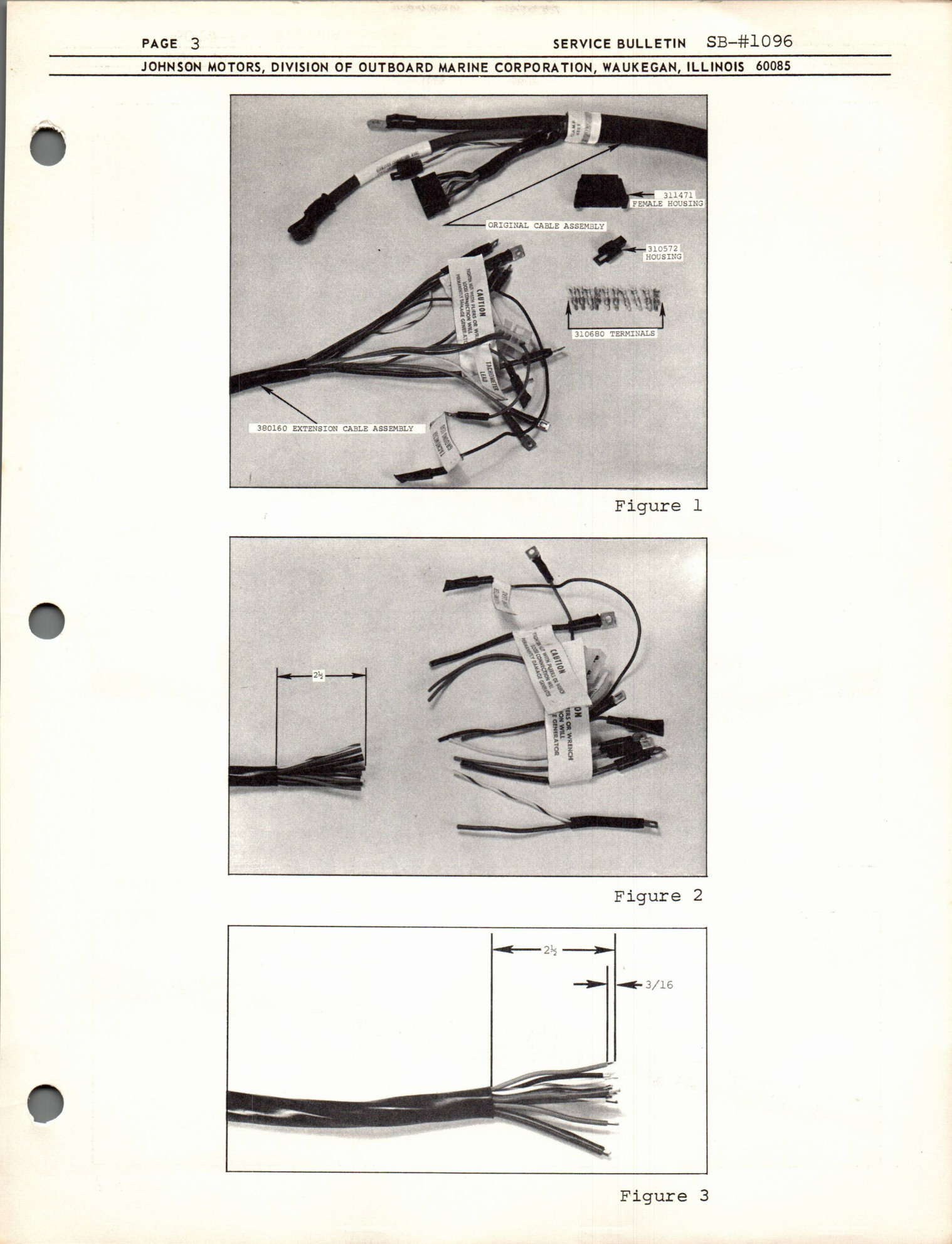
Required Parts (Figure 1)
1 Cable Assembly 380160
11 Terminals 310680
1 Housing 310572
1 Housing 311471
A. CAREFULLY cut all of the wires that extend from the dash panel end of a 380160 Switch Cable Assembly approximately 2½" from the end of the outer black insulation. It is very important that these be square clean cuts so that all of the wires are of the same length after the cuts are made. (Figure 2)
B. Carefully strip back, for a distance of 3/16", all of the wires that you cut off in Step A above. (Figure 3)
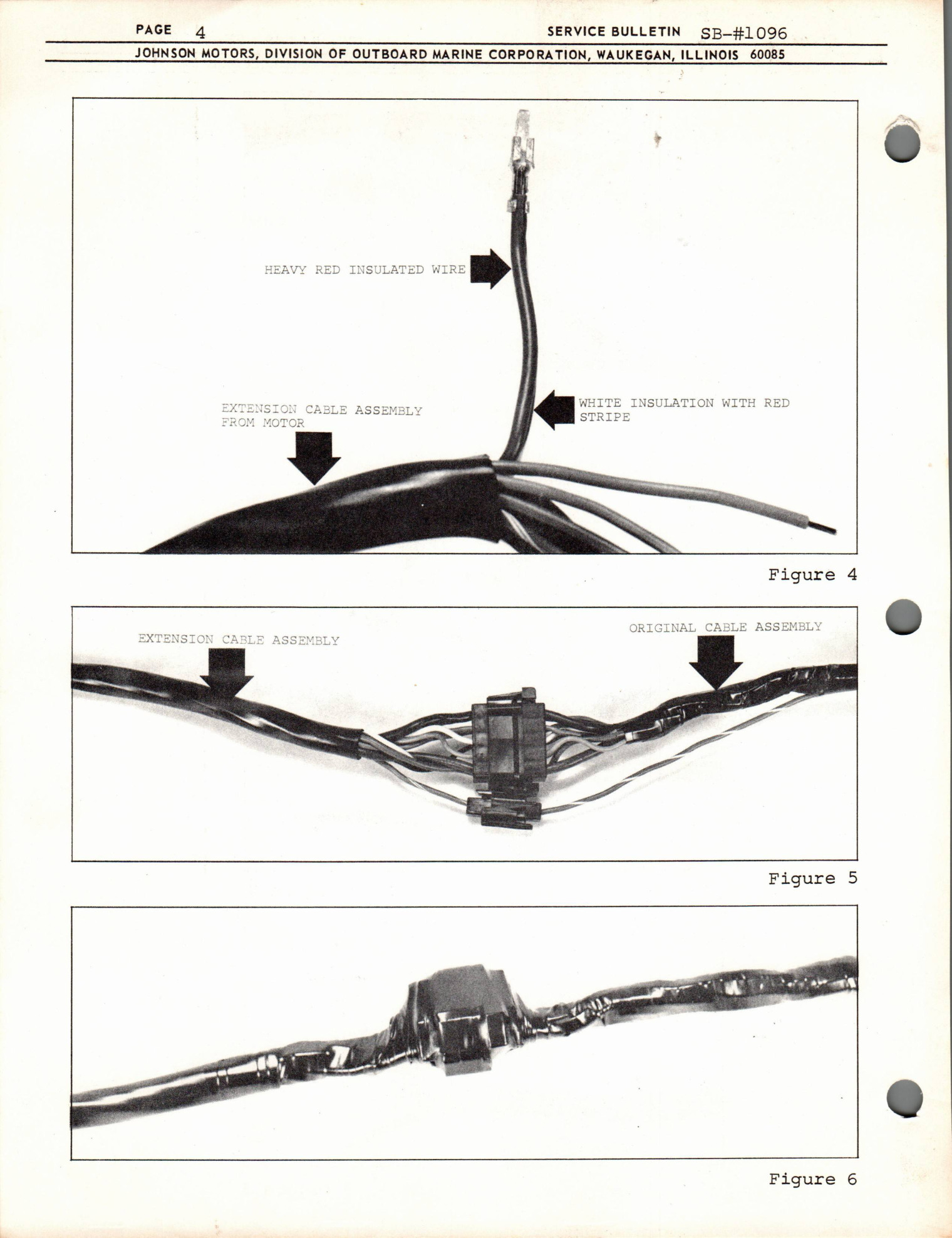
C. Locate the heavy wire with the red insulation and the white wire with the red stripe in the insulation and insert them in the same 310680 terminal. (Figure 4)
D. Insert each of the remaining stripped wires in a 310680 terminal and crimp the clamps of the terminals around the insulation of each wire AS SHOWN IN FIGURE 4.
E. Next, crimp the remaining clamps of the terminals to the stripped portion of the wires and carefully solder each connection, using only ROSIN Core solder.
CAUTION
DO NOT USE ACID CORE SOLDER!
F. Line up the 311471 Housing for the dash panel end of extension cable assembly with the Male Housing on the rear end of the original cable assembly and push the assembled terminals from the extension cable assembly into the 311471 connector, according to the color code of the wires in the male housing on the rear end of the original cable assembly.
PAGE 2 SERVICE BULLETIN SB-1096
JOHNSON MOTORS, DIVISION OF OUTBOARD MARINE CORPORATION, WAUKEGAN, ILLINOIS 60085
JOHNSON MOTORS, DIVISION OF OUTBOARD MARINE CORPORATION, WAUKEGAN, ILLINOIS 60085
G. Since the heavy red wire and the white wire with the red stripe in it were installed together in the same terminal (Step C above), there will be one blank terminal receptacle in the 311471 Housing. The terminal with the red wire and the white wire with the red stripe in it should engage the terminal receptacle of the 311471 Housing that matches up with the terminal receptacle in the housing on the rear end of the original cable assembly containing the heavy red insulated wire.
H. The red wire with the white stripe in it should remain plugged into the 310572 Housing of the original cable assembly.
I. All that remains to complete this procedure is to:
1. Connect the terminal housing halves. (Figure 5).
2. Check each terminal housing to see that the color coding of the wires in each corresponds with that of the other.
3. Check to see that none of the terminals were "backed out" of their housing when the terminal housing halves were connected.
4. Carefully and neatly wrap the splice with plastic insulating electrical tape. (Figure 6)
JOHNSON MOTORS
N. Peter Hansen
Administrative Assistant
NPH:rm
NOTE: Post on your V4-75 H.P., V4-80 H.P., VM-90 H.P. and VM-100 H.P. Indexes under the heading "Electrical".
Parts reference
Switch cable assembly 380160 (1); terminals 310680 (11); housing 310572 (1); housing 311471 (1).
Applications: V4A-17 through V4A-18 and V4M(L)-11 through V4M(L)-12. Factory instructions specify rosin-core solder and prohibit acid-core solder.