Johnson Service Bulletin SB-1111 - Capacitor Discharge Ignition System
October 1966. Johnson introduced capacitor discharge ignition on the 1967 V4TL-13 100 H.P. outboard, replacing conventional breaker points and condenser with a distributor sensor and sealed electronic pack.

October, 1966
SUBJECT: AN INTRODUCTION TO THE CAPACITOR DISCHARGE IGNITION SYSTEM
ON MODELS: V4TL-13, 100 H.P.
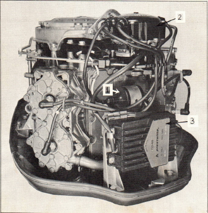
The new capacitor discharge (C.D.) ignition system, which is standard equipment on all 1967 - 100 h.p. engines, consists of three major electronic components. These are (1), a Pulse Transformer, (2) a Sensor (located within the distributor), and (3) an Electronic Pack (see Figure 1). The Pulse Transformer replaces the conventional ignition coil while the Sensor replaces the breaker points and condenser. The Electronic Pack, which is completely sealed in epoxy, is attached to a bracket on the lower rear motor cover.
JOHNSON MOTORS, DIVISION OF OUTBOARD MARINE CORPORATION, WAUKEGAN, ILLINOIS 60085
CAUTION
DO NOT ATTEMPT TO OPEN THE ELECTRONIC PACK AS THIS WILL VOID THE WARRANTY.
To compliment the C.D. Ignition system, special surface gap spark plugs are used. These are Champion L-19V (OMC Part Number 381992).
The C.D. Ignition system has proven to be extremely trouble free and durable in operation. However, since this system is new, any operating malfunctions will probably make the customer suspicious of the C.D. Ignition system. Should a customer complaint place the C.D. Ignition system under suspicion, the following precautions and trouble shooting procedure should be followed.
A. PRECAUTIONS TO BE OBSERVED WHILE TROUBLE SHOOTING THE C.D. IGNITION SYSTEM
Do not attempt to operate the engine without a battery in the system. Damage to the ignition components will result.
Do not attempt to test the Pulse Transformer on a conventional ignition coil tester. This could, under certain conditions, result in damage to the component.
Whenever the trouble shooting procedure requires a check for spark discharges, Do Not hold the high tension lead in your hand. This system produces high voltages at cranking speed which could result in severe electrical shock.
B. TROUBLE SHOOTING THE C.D. IGNITION SYSTEM
NOTE
A malfunction in the system will result in (1) engine miss, (2) engine surge, (3) engine will not run.
Engine missing or surging may also be caused by insufficient, contaminated or excessive fuel. After determining that this condition is not caused by carburetion, proceed (in order listed) to check the ignition system.
1. WIRING. Check all wiring associated with the system for any loose or corroded terminal connections and plug-in connections. Make sure of a clean, tight connection from the negative (-) terminal of the pulse transformer to ground at the voltage regulator. Also check for a clean, tight battery ground cable connection. Check all high tension leads for cracked or oil soaked insulation. The high tension leads should also be checked with an ohmmeter to locate any excessive resistance or opens. Check for correct battery polarity (negative ground). Make sure battery cable connections are clean and tight.
JOHNSON MOTORS, DIVISION OF OUTBOARD MARINE CORPORATION, WAUKEGAN, ILLINOIS 60085
2. TIMING. The timing of the engine should not change during normal engine operation. However, if the seal is off of the adjustment screw, or if the electronic pack has been replaced, the timing should be checked as follows:
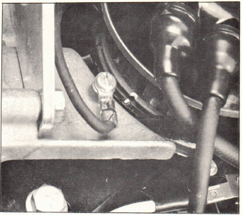
a. With the timing light connected to No. 1 cylinder, start the engine and set engine speed to 500 r.p.m. (in gear). The timing marks on the distributor housing and pulley should line up (figure 2). If the timing marks do not line up, check for damaged or missing distributor keys or distributor shaft keyways allowing pulley or sensor rotor to move, or sensor not properly located on mounting pin. Timing must be correct before proceeding.
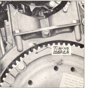
b. With the timing light still connected to No. 1 cylinder, run engine to 4500 r.p.m. (in gear). The timing mark on the flywheel must fall within the square timing mark on the ring gear guard (fig. 3). If necessary, move sealed adjustment screw to obtain proper setting. It is suggested that you reseal the adjustment screw to prevent further adjustments.
3. SPARK PLUGS. The spark plugs should be removed and examined. If the center electrode has worn to a point where it is below the ceramic, it should be replaced. Naturally, any plug which has a cracked insulator or shows signs of damage or mistreatment should be replaced.
JOHNSON MOTORS, DIVISION OF OUTBOARD MARINE CORPORATION, WAUKEGAN, ILLINOIS 60085
4. PULSE TRANSFORMER. Check both terminal studs to determine if excessive tightening has caused the studs to become loose and cause an intermittent open. Check for any cracks or carbonized tracks. Replace the pulse transformer if any of these conditions are found. Remove the pulse transformer to distributor cap lead at the distributor. Using insulated pliers, hold the lead approximately 3/8" from the engine block. Crank the engine and check for spark discharges. A good pulse transformer will produce a spark which will easily jump this gap. If there is any doubt as to the output of the pulse transformer, it should be replaced to determine if it is the source of the trouble.
5. ELECTRONIC PACK. Remove the green lead from the positive (+) terminal of the pulse transformer. Connect a #57 bulb from the disconnected green lead to the negative (-) terminal of the pulse transformer. Crank the engine while observing the bulb. A glowing flicker of the bulb at each firing pulse indicates the Sensor and Electronic Pack are functioning properly. Proceed to Step 6. If a glowing flicker of the bulb is not observed, the Electronic Pack is defective and must be replaced.
6. If a light is observed in Step 5, and no spark discharge can be observed, as in Step 4, the Pulse Transformer is defective and should be replaced.
7. DISTRIBUTOR. The distributor cap and rotor should be inspected for any cracks or carbonized tracks. Replace any defective component.
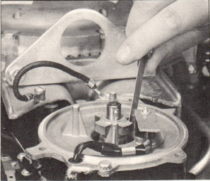
8. SENSOR. Position the sensor rotor as shown in Figure 4. Turn the ignition switch on and pass a feeler gauge or similar tool across the face of the sensor. If sparks are observed from the transformer high tension lead each time this is done, the sensor is good, which might indicate the air gap is not properly set at .028". (See Figure 5.)
JOHNSON MOTORS, DIVISION OF OUTBOARD MARINE CORPORATION, WAUKEGAN, ILLINOIS 60085
8. (Cont’d) If sparks are not observed, disconnect the sensor leads and, using a short jumper wire, intermittently bridge the disconnected sensor leads. If sparks are observed, replace the sensor.
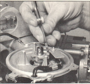
NOTE: Erratic high speed operation can be caused by a sensor which is loose and moving during engine operation, or if the air gap is greater than .028".
DO’S AND DON’TS FOR C.D. IGNITION SYSTEMS
1. DO make sure of clean, tight connections on all wiring, especially the black lead from the Pulse Transformer negative (-) terminal to ground at voltage regulator.
2. DO make sure correct battery polarity is observed (negative ground) and that battery cable and ammeter connections are clean and tight. (Owner should be cautioned to check this periodically as preventive maintenance).
3. DO make sure the plug-in connectors are fully engaged and the terminals are free of corrosion.
4. DO make sure all wiring is located properly so that it will not rub against any sharp metal edges. Vibration would eventually wear a hole in the insulation and result in a service problem that might be difficult to locate.
5. DO make sure accurate test equipment is used when trouble shooting the system.
6. DO make sure, when installing or replacing the Pulse Transformer, that the green lead is connected to the positive (+) terminal and the black lead is connected to the negative (-) terminal.
7. DO use proper tools when installing system components.
JOHNSON MOTORS, DIVISION OF OUTBOARD MARINE CORPORATION, WAUKEGAN, ILLINOIS 60085
DO NOT
1. DO NOT attempt to open the Electronic Pack, as this will void any warranty consideration.
2. DO NOT attempt to check the Pulse Transformer on a conventional coil tester. Under certain conditions, this will damage the component.*
3. DO NOT pull on leads at the Electronic Pack or Distributor.
4. DO NOT open or close any plug-in connectors while the ignition switch is on.
5. DO NOT set timing to other than specifications.
6. DO NOT hold the spark plug wires with your hand while checking for spark discharges. A severe electrical shock will result. Use insulated pliers designed for this purpose.
7. DO NOT attempt any tests except those listed in the trouble shooting procedure.
8. DO NOT connect an electric tachometer to this system unless it is a type which has been approved for use with this system.
9. DO NOT connect any radio noise suppression capacitors to this system unless they have been approved for use with this system.
10. DO NOT connect the system to any voltage source other than 12 volt negative ground.
11. DO NOT bench test this system without proper ground connections and these ground connections to be as short as possible.
JOHNSON MOTORS
Carl Klawonn Administrative Assistant
CK:rs
NOTE: Post on your V4M, 100 H.P. Index under the heading "Ignition"
*Special instructions for testing the Pulse Transformer are forthcoming.
Historical parts and service references
Champion L-19V surface-gap spark plug, OMC part number 381992. Factory timing checks: 500 RPM and 4500 RPM in gear. Distributor sensor air gap: 0.028 inch.
This bulletin cautions against opening the sealed electronic pack, using a conventional coil tester on the pulse transformer, or checking high-voltage spark by hand. It states that separate pulse-transformer testing instructions were forthcoming.