Johnson Service Bulletin SB-1117 - Folding 3 H.P. Driveshaft Removal
Issued December 1966 for the 1967 JWF-22 and JHF-22 folding 3 H.P. outboards. This bulletin explains the roll-pin alignment needed to lift the powerhead and shows a simple fixture to support the driveshaft during pin removal.

SUBJECT: POWERHEAD AND/OR UPPER DRIVESHAFT REMOVAL -
1967 - FOLDING 3 H.P.
ON MODELS: JWF-22 AND JHF-22
Removal of the powerhead and adaptor assembly on the 1967 Folding 3 H.P. motor can be quite frustrating if you are not aware that a roll pin is present in the top end of the driveshaft. This pin must line up with the grooves in the adaptor plate before disassembly of the powerhead from the exhaust housing can be achieved. (Figure 1)
Proper alignment of this pin is accomplished as follows:
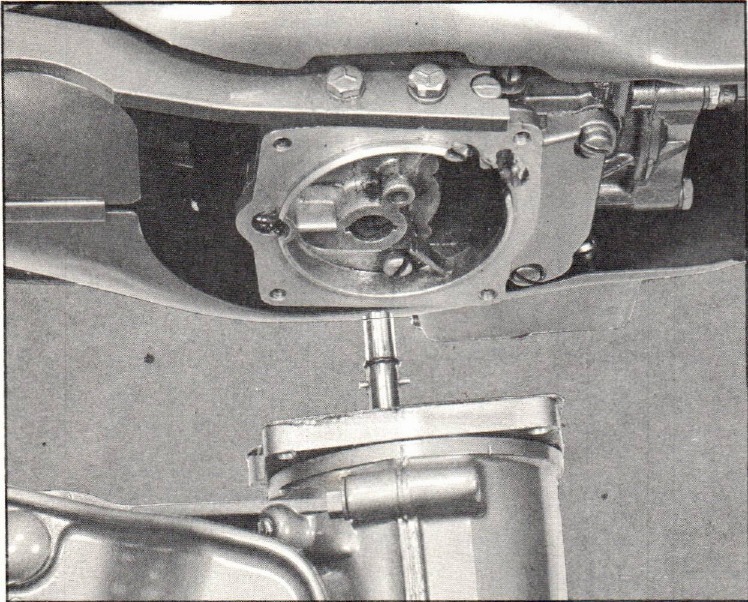
- Fold the gearcase so the bottom end of the upper driveshaft is visible.
- Note the pin at this location which engages with the lower driveshaft coupling. This pin is in direct relationship with the one above.
- Rotate the driveshaft to position the lower pin so that it bisects the powerhead, front to rear.
The roll pin at the top end of the driveshaft should now be in the correct position to enable the powerhead to be lifted off.
In order to remove the driveshaft from the exhaust housing, it is first necessary to remove the powerhead.
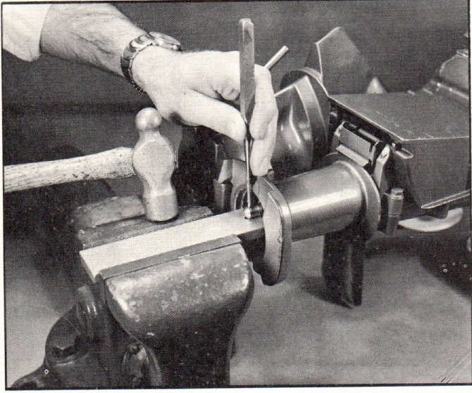
Then the pin which engages with the lower driveshaft coupling must be cut off or removed. It can be punched out if care is exercised and proper support given the driveshaft.
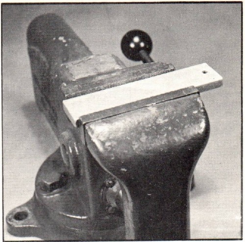
A simple fixture can be fabricated from a piece of cold rolled steel 3/8" thick x 1-1/2" wide x 5" or 6" inches long. Drill a 1/4" hole 1/2" from one end and in the center (Fig. 2). The fixture, clamped in a vise, will sufficiently support the driveshaft while the pin is being punched out. (Figure 3).
CAUTION
ATTEMPTS TO PUNCH THE PIN OUT WITHOUT SUCH SUPPORT CAN VERY EASILY RESULT IN EXHAUST HOUSING DAMAGE.
Upon reassembly, a new pin can easily be driven into place, again using this fixture for support.
Carl Klawonn
Administrative Assistant
CK:rs
NOTE: Post on your JW-JH Index under the headings "Powerhead" and "Lower Unit".
Service reference
The original bulletin cautions that driving out the lower coupling pin without properly supporting the driveshaft can damage the exhaust housing. Figures 2 and 3 illustrate the suggested fixture and its use.