Johnson Service Bulletin SB-1130 - Timing and Synchronizing, 1958-59 50 H.P.
June 1967. Factory procedures for timing the magneto and synchronizing the carburetor on 1958-59 Johnson V-50 engines, illustrated with six original service photographs.

June, 1967 SB-#1130
SUBJECT: TIMING AND SYNCHRONIZING - 1958-59 50 H.P. MODELS
There seems to be a considerable amount of confusion, in the field, concerning the proper method of timing and synchronizing ignition and carburetion of the subject engines. Although the V-50 is similar in appearance to later model V-4 engines, there is a definite difference in the subject procedure. To assist you in the proper method of synchronization, the following bulletin has been prepared.
TIMING - To be sure the magneto is properly timed with the crankshaft proceed as follows:
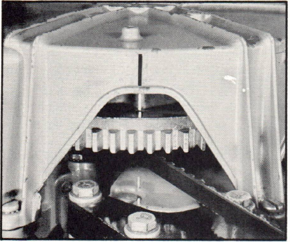
- Align the timing marks on the starter housing, flywheel and water passage cover as shown in Figure 1.
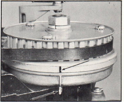
- The timing marks on the magneto pulley and the magneto bracket, as shown by the two arrows, should be aligned when viewed as shown in Figure 2. If the marks are aligned, the magneto is properly timed - if not, remove the pulley cover, slip the belt off, align the marks, and replace the belt. Replace the cover and be sure screws are tight.
JOHNSON MOTORS, DIVISION OF OUTBOARD MARINE CORPORATION, WAUKEGAN, ILLINOIS 60085
SYNCHRONIZING - To be sure the carburetor is properly synchronized with the magneto proceed as follows: (Note: This procedure differs from that used on 60, 75 and 80 H.P. magneto models in that the magneto is not placed in full advance to adjust the position of the control shaft arm.)
- Align the synchronizing mark on the magneto breaker plate between the two timing marks as shown in Fig. 2.
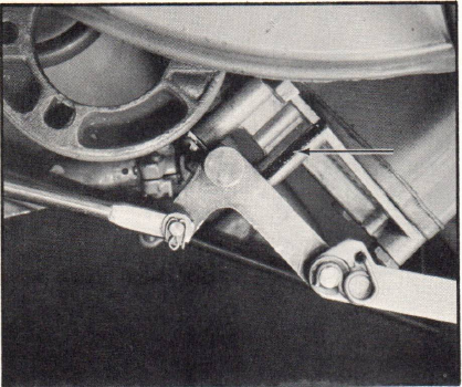
- With the synchronizing mark in this position, the side of the control shaft arm should be flush with the end of the alignment mark (arrow) on the control shaft bracket when viewed from directly above, as shown in Figure 3.
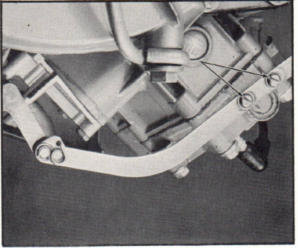
- If the arm is not positioned correctly, loosen the two linkage screws (Figure 4) and make the necessary adjustment. Be sure the screws are retightened.
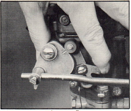
- Loosen the cam follower screw. While holding the throttle arm in the closed position, as shown, align the mark on the cam with the center of the roller shaft (Figure 5). Be sure the roller is contacting the cam and tighten the cam follower screw.
- Shift motor into forward gear and move the magneto to full advance position by hand.
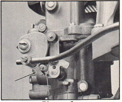
- Loosen the control rod anchor screw and rotate the cam until the finger on the bottom of the cam (arrow Fig. 6) just touches the nylon roller on the throttle arm. Retighten control rod anchor screw.
JOHNSON MOTORS, DIVISION OF OUTBOARD MARINE CORPORATION, WAUKEGAN, ILLINOIS 60085
Care with each of the above steps will assure you of the V-50 being correctly timed and the magneto and carburetor properly synchronized.
J. R. Penland
Service Promotion Manager
JRP/rkm
NOTE: Post on your V-4 50 H.P. Index under the heading "Ignition".