Johnson Service Bulletin SB-1149
November 1967 - Introduction to Capacitive Discharge Ignition with Breaker Points. Factory instructions for 55, 65 and 85 HP Johnson outboards, covering ignition components, timing, synchronization and electrical diagnosis. The original six-page document is reproduced below. The two photographic reference pages are retained as complete scans.

November, 1967
SUBJECT: INTRODUCTION TO CAPACITIVE DISCHARGE IGNITION WITH BREAKER POINTS
ON MODELS: TR(L)-10, 55 H.P.
VX(L)-14, 65 H.P.
V4S(L) - V4A(L)-20, 85 H.P.
All of the above models now have Capacitive Discharge Ignition systems taking advantage of the use of the "long-life" surface gap spark plugs introduced and used so successfully on the 100 H.P. in 1967.
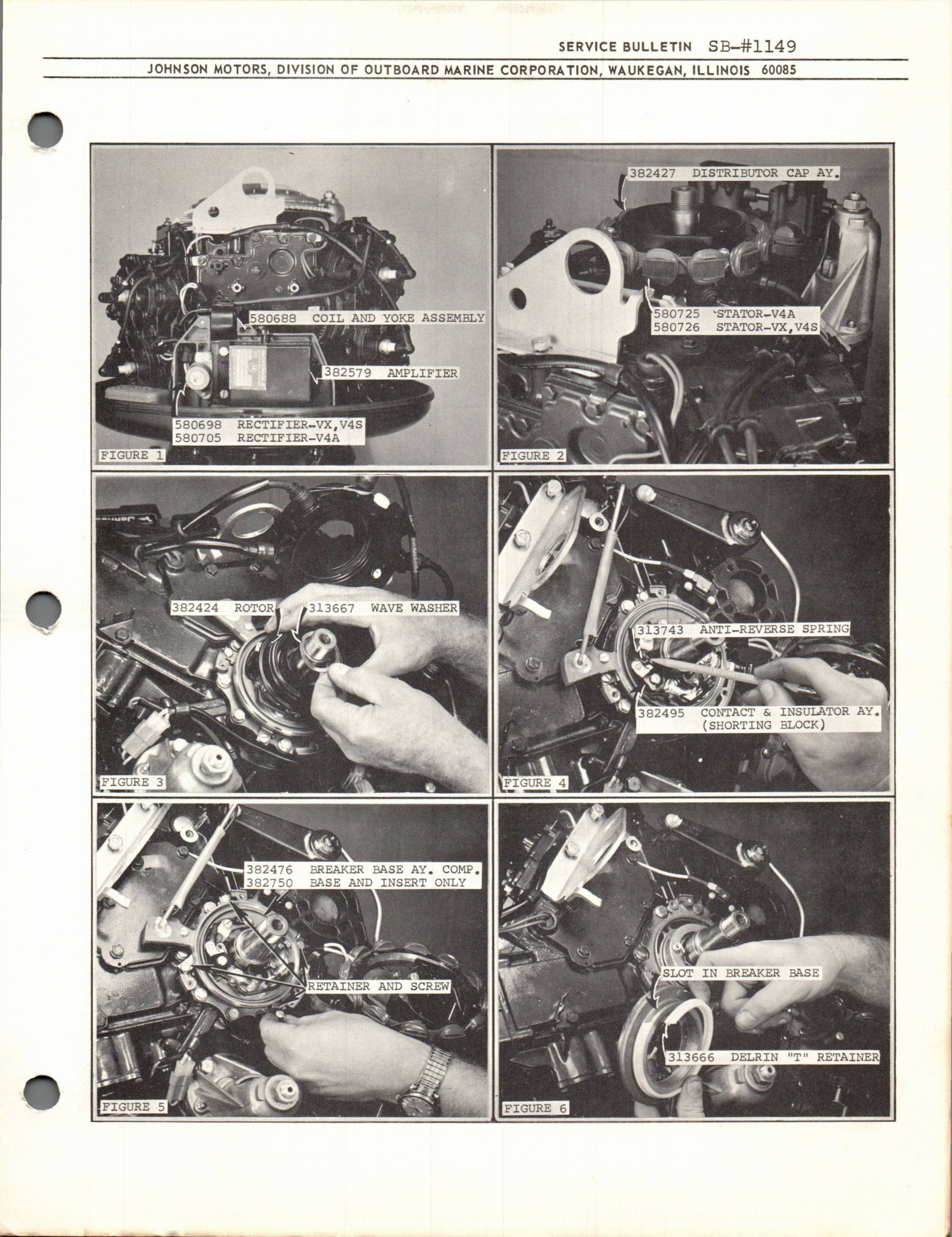
The electronic "Pulse Pack" or amplifier is mounted on a bracket at the rear of the engine. The new ignition coil is also mounted on this bracket along with the miniaturized rectifier assembly required for the charging systems (Fig. 1). The distributor has been located under the flywheel, thus eliminating the need for a driving belt as the breakers and rotor are operated directly by the crankshaft (Fig. 2).
With this ignition system, the breaker points draw very little current, and protected as they are under the flywheel, will require only a minimum amount of attention throughout the life of the engine.
The following paragraphs are written to acquaint you with the new parts and set-up procedures unique to this system. Although centered around the 65 and 85 H.P. models, this information applies in general to the 55 H.P. also; the basic differences being relative to breaker point setting and theory. A supplemental bulletin at a later date will cover these differences.
With the flywheel removed, the alternator stator assembly and distributor cap are easily removed, exposing the rotor assembly and breaker points. IMPORTANT NOTE: The three Phillips head screws securing the stator and distributor cap must be installed at 4-5 foot pounds and have Loctite grade "H" or "EV" applied to the threads. Before applying Loctite, be sure tapped holes and screws are free of oil! You will note the presence of a wave washer within the top of the rotor (Fig. 3) which, when the flywheel is installed, acts to provide stability to the rotor. Without the wave washer, the rotor would wobble creating a very unsatisfactory spark distribution and would shortly cause destruction of the rotor key.
Unlike distributors of the past, the Anti-Reverse mechanism consists of a spring clip, clipped around the crankshaft. In clockwise rotation, the crankshaft holds this clip away from the contact and insula-
tor assembly (shorting block), allowing continuity between the breakers and amplifier (Fig. 4). Should the engine attempt to run counter-clockwise, the spring clip is pulled by the rotation of the crankshaft against the shorting block, thus shorting out the ignition. This Anti-Reverse spring must not bind when the breaker base is installed and must be generously lubricated with Shell Alvania EP#2 grease which is a high temperature, high speed grease.
The breaker base is held in place by four retaining clips and screws (Fig. 5). These clips engage a Delrin "T" ring which fits around the slotted breaker base (Fig. 6). A secure mounting is thus achieved yet allowing the breaker base to pivot freely. The breaker base has a brass bushing cast in place which pilots on the crankcase head. Due to the close tolerance between the moving parts, the presence of any amount of dirt, chips, nicks, etc., will cause difficulty in rotating the breaker base. After cleaning all parts involved, a small amount of light weight oil is applied to the brass bushing.
Timing is adjusted at any R.P.M. above the point at which the throttle control arm stops its advancing movement. First be sure points are correctly gapped at .010 inches, then using a timing light, the full advance stop screw (Fig. 7) is adjusted so the boss on the flywheel lines up with the pointer on the lifting bracket (Fig. 8). NOTE: The straight boss on the flywheel is for No. 1 cylinder and wedge shaped boss is for No. 2 cylinder.
Adjustment of the carburetor linkage on the V's is basically the same as in the past. Position the throttle cam so that the synchronizing mark falls in line with the center of the cam follower roller (Fig. 9). Loosen the clamp screw and move the throttle arm to its limit to close the throttle valves. Make sure the roller is contacting the cam, and retighten clamp screw.
To synchronize the carburetor and distributor linkage, advance the throttle lever to full open position. At this position, points A and B should simultaneously bottom against their respective stops (Fig. 10). If such a condition can not be achieved through adjustment of C, a slight clearance at point A will be necessary.
A starter safety switch is still employed as in the past and is also located under the flywheel. It is actuated directly by the breaker base and it should be set to break continuity just as the switch plunger drops off the highest part of the cam onto the ramp as the throttle is being advanced (Fig. 11). For a running check, the following test can be made: While engine is stopped and engaged in forward gear, advance the throttle to full power. Holding the key on start position, slowly retard the throttle until the starter motor engages and engine starts. At this time, the engine should turn between 1000 and 1800 R.P.M.
Diagnosis of ignition problems consists of only a few simple steps as outlined. Engine missing and surging may be caused by insufficient, contaminated, or excessive fuel. After determining that these conditions are not caused by carburetion, proceed (in order listed) to check the ignition system.
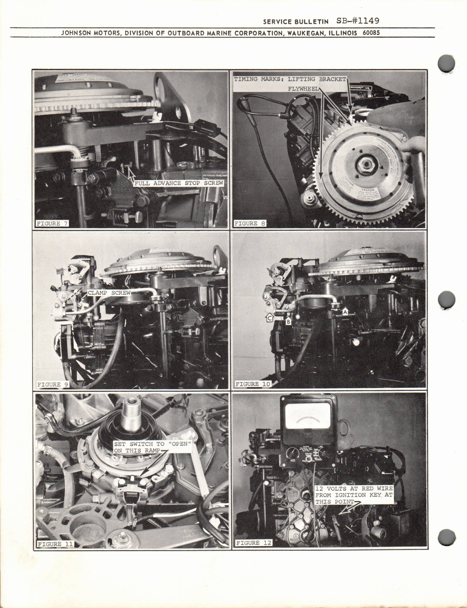
1. WIRING - Check all wiring associated with the system for any loose or corroded terminal connections and plug-in connections. Check for clean, tight battery connections and correct polarity (negative ground). The high tension leads should also be checked with an ohmmeter to locate any excessive resistance or opens. Determine if full battery voltage (12 volts) is available at the red wire leading to the amplifier (Fig. 12). Unlike the 100 H.P. "CD" ignition system, there is no external suppressor in the circuit. This has been incorporated within the rectifiers on the 55, 65 and 85 H.P. models.
2. DISTRIBUTOR - The distributor cap and rotor should be inspected for any cracks or punctures using regular high tension probing techniques. Also check the anti-reverse shorting block to be sure it isn't shorting to ground and make certain the Anti-Reverse spring is free to move.
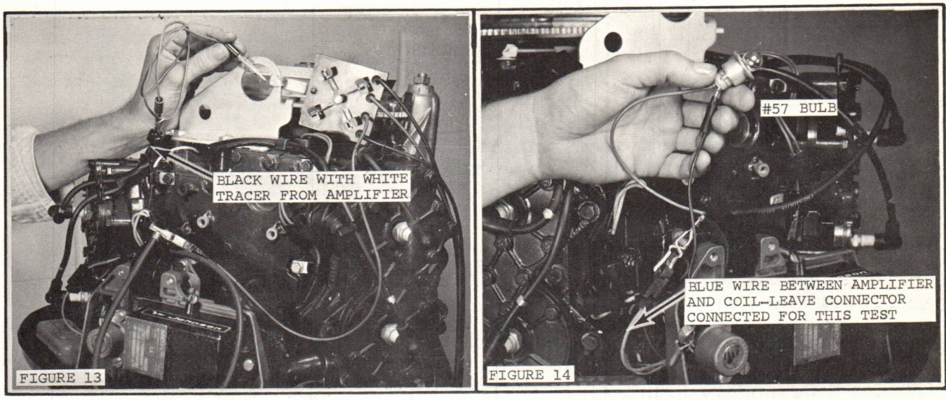
3. Disconnect the high tension lead from the coil at the distributor cap. CAUTION: This is a screw-in connection. Position the lead approximately 3/8" from ground or use a "sparky" as illustrated in Figure 13 and crank over the engine. If sparks are observed, re-check step #2. If sparks are not observed, go on to step #4.
4. Disconnect the connector in the black wire with a white tracer which connects the points to the amplifier. With the ignition key on and using a jumper connected to the amplifier portion of the above lead, intermittently touch ground while the high tension lead is positioned as described above in step #3 (Fig. 13). Sparks should occur each time the jumper is lifted from ground. If sparks occur, this indicates the amplifier and coil are O.K. and the trouble lies within the breaker points and/or Anti-Reverse mechanism. Points should be checked for .010" gap and the related wires inspected for shorts and/or open circuits.
5. If sparks do not occur during step #4, the amplifier is then checked using a #57 bulb as illustrated in Figure 14. Connect one lead of the test bulb into the connector in blue wire from amplifier to coil
without disconnecting the coil from the circuit. Connect the other lead to ground. Intermittent illumination of the bulb while cranking is indicative of a good amplifier. (The bulb will not light if both of the breaker points remain in an open or closed position while cranking, or if a short exists in the circuit to the breaker points, or if the Anti-Reverse mechanism is malfunctioning.)
6. If the bulb does not light in step #5, disconnect the black wire with a white tracer leading to the points and intermittently touch ground with a jumper wire as described in step #4. If the bulb still does not light, replace the amplifier.
7. All previous check points and adjustments having been successfully completed, the coil should be checked in accordance with the following specifications:
Graham Coil & Condenser Tester:
Secondary Continuity ................. 3000 ohms maximum
Primary Continuity ................... 1.2 ohms maximum
Coil Index ........................... 60
Coil Test ............................ 9 minimum
Gap Index ............................ 50 maximum
Merc-O-Tronic Magneto Analyzer, Models 98 & 88:
In order to test the coil with this analyzer, a special adaptor, Merc-O-Tronic model 55-980 C.D.A. is required. (See Service Promotion Bulletin SPB-396 dated August, 1967.) Complete instructions and specifications are supplied with each adaptor.
The ignition system on the 100 H.P. remains virtually unchanged in principle and operation. It is important to note, however, that the electrical characteristics of the 1968 Pulse Pack do not permit interchangeability with 1967 units. The distributor, including the Sensor unit has been relocated under the flywheel. Diagnosis of the system remains unchanged from 1967.
Incidentally, all 1968 Johnson outboard models with the exception of the 100 H.P. V4T(L) and 115 H.P. GT can use the OMC Universal tachometer.
Carl Klawonn
Administrative Assistant
CK/rkm
NOTE: Post on your VX - 60 H.P. and V4 - 80 H.P. Indexes under the heading "Ignition".
Historical parts and equipment reference
Factory-identified components shown in Figures 1-6:
- 580688 - Coil and yoke assembly
- 382579 - Amplifier
- 580698 - Rectifier (VX, V4S)
- 580705 - Rectifier (V4A)
- 382427 - Distributor cap assembly
- 580725 - Stator (V4A)
- 580726 - Stator (VX, V4S)
- 382424 - Rotor
- 313667 - Wave washer
- 313743 - Anti-reverse spring
- 382495 - Contact and insulator assembly (shorting block)
- 382476 - Breaker base assembly complete
- 382750 - Base and insert only
- 313666 - Delrin T retainer
Testing references: Graham Coil & Condenser Tester; Merc-O-Tronic Magneto Analyzer models 98 and 88; Merc-O-Tronic 55-980 C.D.A. adapter; #57 test bulb; Shell Alvania EP#2 grease; Loctite grade H or EV.
Related factory publication: SPB-396 (referenced in SB-1149; check archive availability).