
March, 1968
SUBJECT: FUNCTION OF VACUUM SWITCH
ON MODELS: TR(L)-10, 55 H.P.
V4TL-14, 100 H.P.
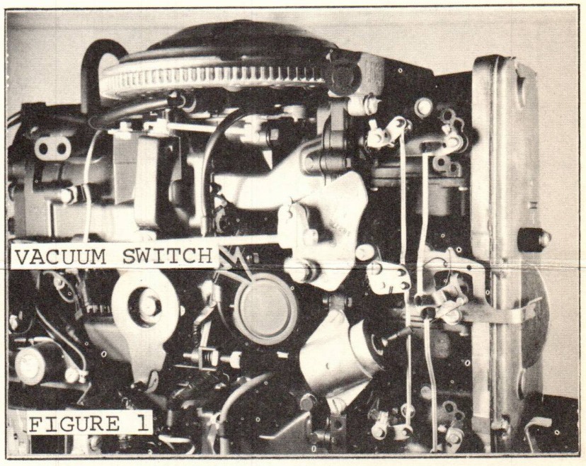
By now, you are probably all aware of the vacuum switch on the above models. This switch serves a different function on each model and the difference will be pointed out here.
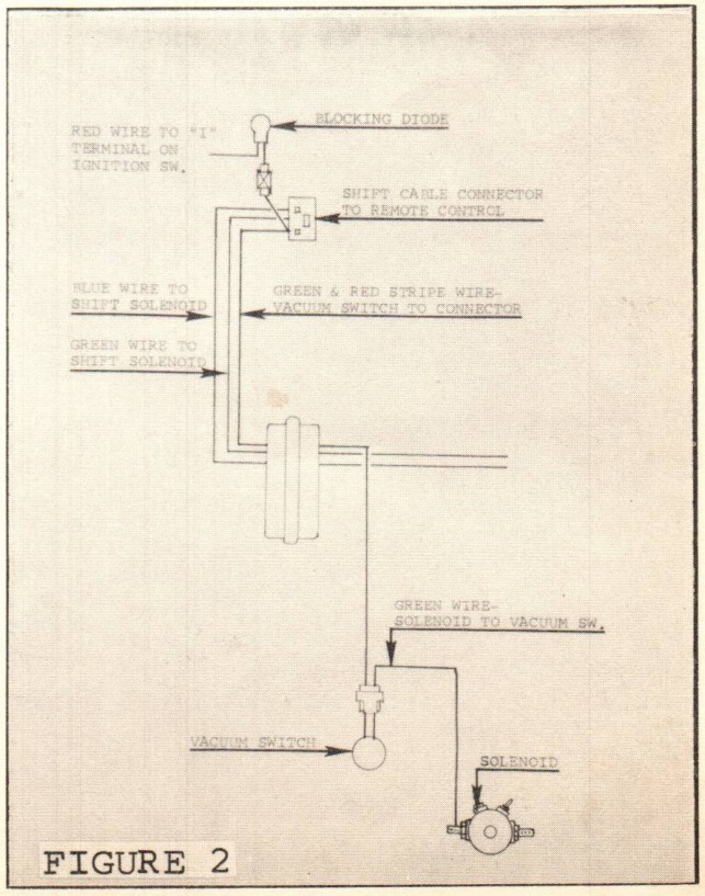
The function of the vacuum switch on the 55 H.P. is to provide an alternate electrical path to the shift control switch while the engine is running. The source of this current is the battery side of the starter solenoid. This is in addition to the current from the ignition switch "I" terminal. The second circuit is required so that when the ignition is cut off, the shifting circuit remains completed until the engine stops rotating and vacuum in the switch is lost. (Trace the two circuits illustrated in Figure 2.)
Without the second circuit, when the ignition is cut off, the engine would automatically shift into forward gear, as it is spring loaded for fail-safe forward engagement. If this shifting is allowed to occur, a forward boat movement could be noticed; the extent of movement dependent upon engine R.P.M. at the time the ignition is cut.
In addition to the vacuum switch, there is one more item in the shift circuit on the 55 H.P. engine which needs pointing out. It is the diode in the lead from the ignition switch "I" terminal to the shift selector switch. (Figures 2 and 3).
JOHNSON MOTORS, DIVISION OF OUTBOARD MARINE CORPORATION, WAUKEGAN, ILLINOIS 60085
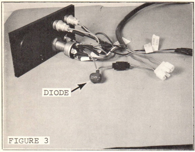
The purpose of the diode is to isolate the second electrical path of the vacuum switch circuit from the "I" terminal of the ignition switch. Should the diode fail in a shorted condition, the current thru the closed vacuum switch would then supply current to the ignition and you could not stop the engine by turning the ignition to the "off" position.
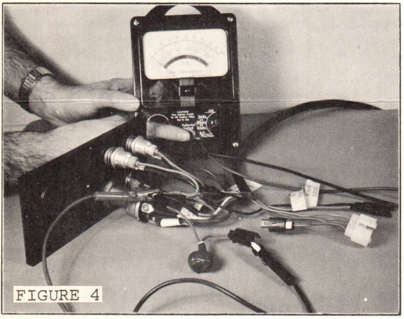
Should the diode fail in an "open" condition, it would probably go unnoticed as the vacuum switch closes very readily, thus supplying the required current to obtain the desired clutch dog position. Whenever either failure is suspected, a quick check of the diode should be made with an ohmmeter or continuity light. (Figure 4).
Function of the vacuum switch on the 100 H.P. is to delay the electrical current to the voltage suppressor and subsequently to the Pulse Pack until the engine has been rotated by the starter. After a revolution or two of the engine, the vacuum switch makes contact, completing the ignition circuit.
The above described delay prevents the engine from a possible self-starting condition.
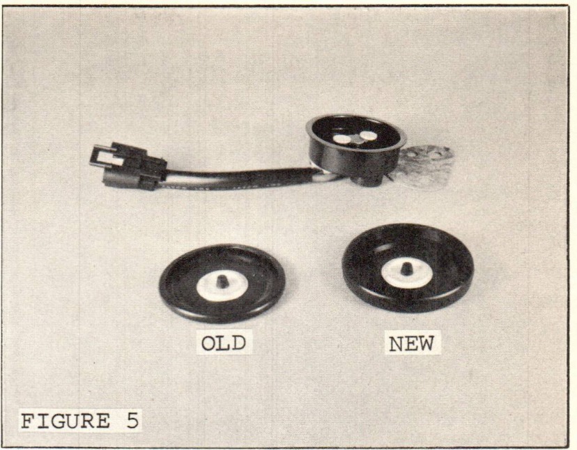
Some improvements have been made in the vacuum switch assembly since it appeared on the first produced engines.
A. The first units shipped did not have the diaphragm covers glued on. "1000 Sealer" can be used for those requiring adhesion.
B. The section of the diaphragm cover which fits over the plastic switch body has been increased to provide more stability (Figure 5).
JOHNSON MOTORS, DIVISION OF OUTBOARD MARINE CORPORATION, WAUKEGAN, ILLINOIS 60085
C. Check valve retainer has been increased in holding power. The improved retainer is P/N 314243 replacing P/N 310389 (Page 15, item #111 of 100 H.P. Parts Catalog).
D. The relief passage in the check valve disc will be eliminated and a small groove in the disc seat will provide the relief passage. This change will be in effect in the very near future.
Your 1968 55 H.P. Preliminary Edition Parts Catalog should be corrected as follows:
Page 15, Item 21- 383161 Spark Plug AC-V40FF, should read 383181 Spark Plug AC-V40FF.
Page 17, Item 28- 314031 Spring Washer, quantity of 2 is correct for the upper, or pivot shoulder bolt. Part Number 315085 is a Nylon Washer and should be shown for use on the bottom shoulder bolts (2 required). Units now being produced use the Nylon Washers in this spot.
Page 23, Item 48- 379526 Switch and Cable Assembly, should read 382661 Switch and Cable Assembly.
Page 23, Item 53- 310617 Transfer should read 314014 Transfer. 314014 is also available in 382855 Decal Set.
Carl Klawonn
Administrative Assistant
CK/rkm