Johnson Service Bulletin SB-1166

Installing #382918 and #382919 Service Gearcases - June 1968. Johnson Motors explains the redesigned water inlet and return tube arrangement used when replacing gearcases on 35 and 40 H.P. models.

Johnson Motors Service Bulletin letterhead

June, 1968 SB-#1166

SUBJECT:   INSTALLING #382918 AND #382919 SERVICE GEARCASES

ON MODELS:  RD-21 thru 30D, 35 and 40 H.P.
            RDS-20 thru 30D, 35 and 40 H.P.

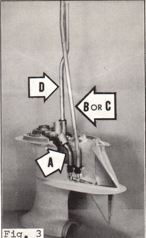
When the occasion arises to install one of the subject gearcases, you will note the gearcase has undergone a redesign which changes the locations of the inlet and return water tubes. Because of the new water tube arrangement, three water tubes are supplied with each gearcase. These are illustrated in figure one. Tube "A" is the water inlet tube; tube "B" is a water return tube for standard length models; tube "C" is a water return tube for 5" longer models. Determine between tubes "B" and "C" which tube is required and lay the other aside. It will not be used.

Figure two illustrates the inlet tube inserted into the new impeller housing cap provided. As illustrated in figure one, the inlet tube has a square cut on one end. This square cut end is inserted in the impeller housing cap and caution must be exercised to not allow it to bottom in the cap. If this happens, the water flow will be restricted. To eliminate this possibility, the inlet tubes are now being angle cut on both ends.
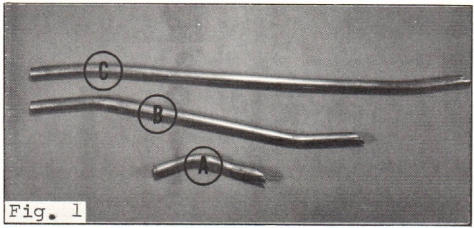
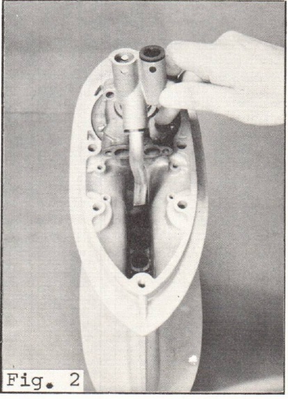
Figure 1 - three supplied water tubes labeled A, B and C
Figure 2 - inlet water tube inserted into impeller housing cap
PAGE 2      SERVICE BULLETIN SB-1166
JOHNSON MOTORS, DIVISION OF OUTBOARD MARINE CORPORATION, WAUKEGAN, ILLINOIS 60085

Figure three is cut away to illustrate the complete arrangement of the water tubes. Please note the location of:  the inlet water tube (A) in the forward hole of the gearcase; and the location of the return water tube (B or C) in the aft hole of the gearcase. Also note that tube "D" is reused from the original installation, and is inserted in the top, starboard hole of the impeller housing cap.

Figure 3 - complete water tube arrangement with A, B or C, and D indicated
JOHNSON MOTORS

Carl Klawonn
Administrative Assistant

CK/rkm

NOTE:  Post on your RD - 35 H.P. and RD - 40 H.P. Indexes under the heading "Lower Unit".