JULY, 1968
SUBJECT: TROUBLE-SHOOTING THE HYDRO-ELECTRIC DRIVE GEAR SHIFT SYSTEM
ON MODEL: TR(L)-10, 55 H.P.
A. LOW HYDRAULIC PRESSURE
1. OIL LEVEL
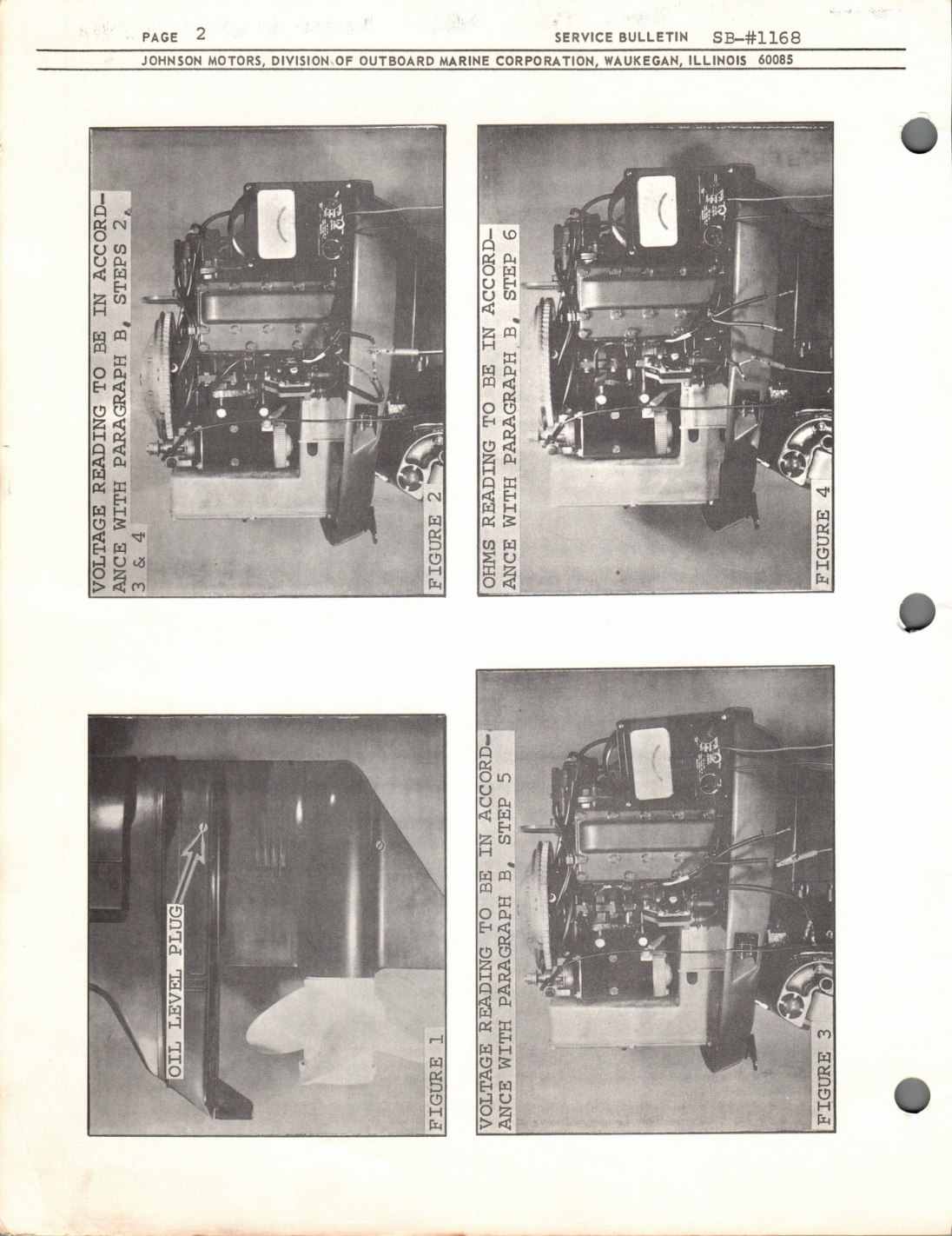
If difficulty is encountered with the Hydro-Electric System, the first thing that should be checked is the gearcase oil level. If the oil level is more than two (2) inches below the oil level plug, conditions may arise under which the hydraulic pump is not adequately supplied with oil (Fig. 1). When this occurs, the hydraulic pump cannot build up sufficient pressure for the shift into reverse and sometimes not even enough pressure for the shift into neutral.
2. WATER IN THE OIL
Similarly, low hydraulic pump pressure may be caused by water in the gearcase oil. To determine the presence of water, remove the bottom gearcase drain plug, drain a small amount of oil into a glass jar and examine its appearance. If the oil is milky in appearance, water is present.
B. PRELIMINARY ELECTRICAL TESTS
The next step in this trouble-shooting procedure is to check if electric current is energizing the shift solenoids. It is best to have the engine hooked up to the battery and electrical system of the boat on which it is used in order to check all components in the system. Then perform the following steps in the order indicated, being certain that the battery in the system is fairly well charged. (Specific gravity 1.220 or higher.)
1. Slide off the insulating sleeves covering the knife disconnects on the green and blue wires of the shift cable located on the port side of the powerhead. Be sure that the bare knife disconnects never contact the engine since this may, in some cases, cause a short circuit.
PAGE 3 SERVICE BULLETIN SB-1168
2. Connect one lead of a DC voltmeter, that has been set to read at least 13 volts full-scale, to the knife disconnect on the green coded wire and the other lead to engine ground (See Fig. 2).
3. With the key switch in the "ON" position, shift the remote control lever from "Forward" to "Neutral" and then to "Reverse" and back again. If the remote control shift switch, instrument cable assembly, and powerhead wiring harness are functioning properly, the Voltmeter reading should be 0 volts when the remote control lever is in the "Forward" position and a minimum of 10 volts when it is in either "Neutral" or "Reverse".
4. Repeat the same procedure for the blue coded wire. If the remote control shift switch, instrument cable assembly and powerhead wiring harness are functioning properly, the Voltmeter reading should be 0 volts when the remote control lever is in either the "Forward" or "Neutral" positions and a minimum of 10 volts when it is in the "Reverse" position.
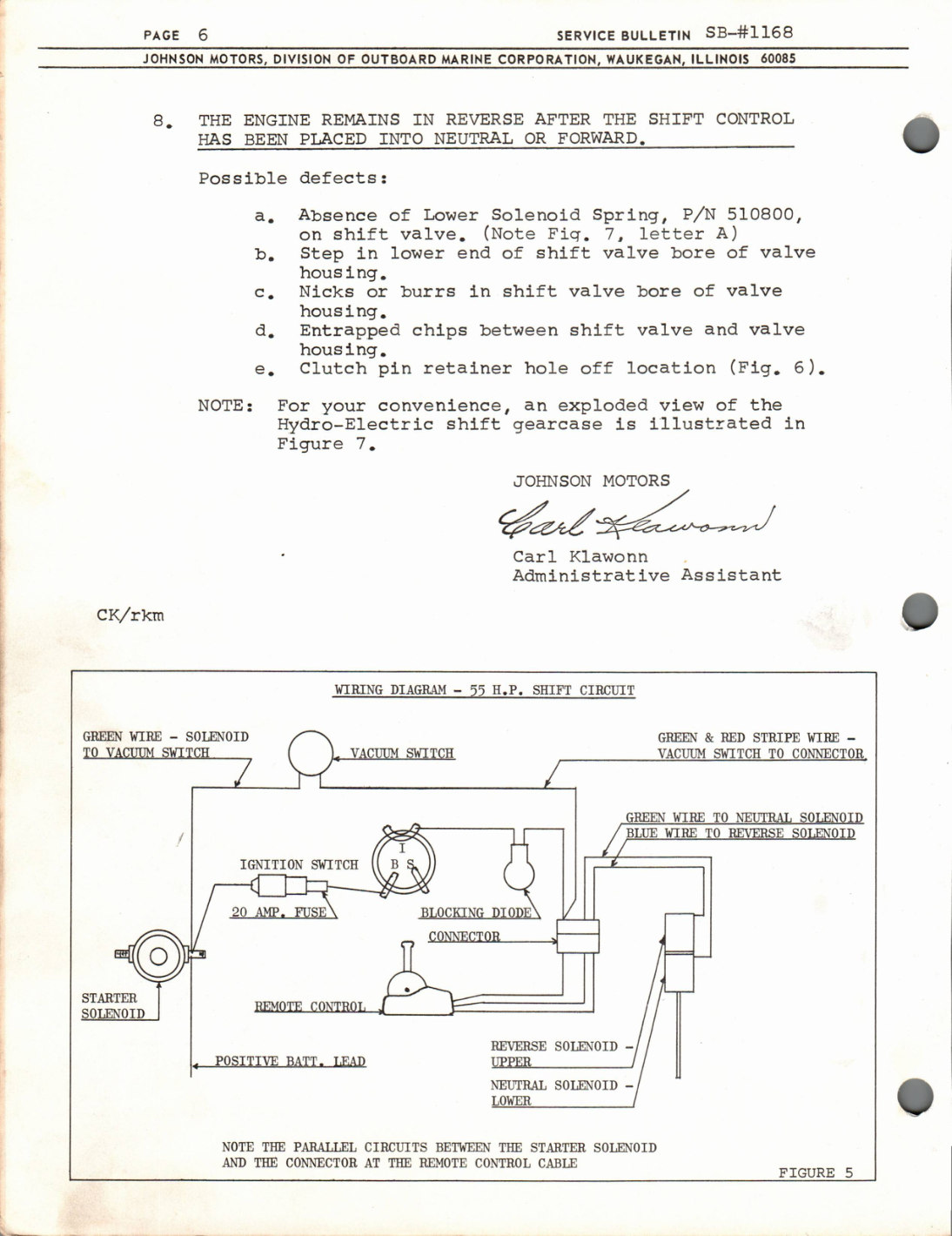
5. If the Voltmeter reading in either step 3 or 4 was less than 10 volts when the remote control lever was in the appropriate position, uncouple the knife disconnects and repeat steps 3 and 4 with the Voltmeter connected first to the green and then the blue coded wire which leads into the powerhead wiring harness (See Fig. 3). These tests will indicate whether the lack of voltage is due to a short circuit in the solenoid(s) or a problem in the control switches and/or wires.
6. If the aforementioned electrical tests do not reveal any problems, disconnect the battery and using an ohmmeter, connect its leads first to the green coded wire and engine ground and then to the blue coded wire and engine ground. The green and blue coded wires, in this case, are those that lead directly to the solenoids, as shown in Figure 4. In each case, a correctly calibrated ohmmeter should read 5 to 6 ohms. A lower reading indicates a partial or complete short in the solenoid. A higher reading indicates a broken wire or connection, or a poorly soldered ground connection within the solenoid. In the case of any of these defects, the Solenoid Assembly, P/N 580776, should be replaced.
NOTE: For your convenience, a sketch of the electrical current for the shift system is illustrated in Figure 5.
C. MECHANICAL TESTS
If everything checked out satisfactorily in the preceding tests, it is now necessary to perform certain mechanical
PAGE 4 SERVICE BULLETIN SB-1168
tests. These tests can be made by running the engine, equipped with a test propeller in a test tank, or on the boat, in which case it should be equipped with a propeller.
--CAUTION--
Regardless of where the engine is tested, be sure that the reverse lock is in the "LOCKED" position, before making any mechanical tests of the Hydro-Electric Shift System.
1. Shift the engine several times at the lowest possible RPM, noting how the engine responds to the "Forward", "Neutral" and "Reverse" positions of the remote control lever.
2. Using a tachometer, set the engine RPM to 1000 RPM in "Forward" and shift several times from "Forward" to "Neutral", "Neutral" to "Reverse", "Reverse" to "Neutral", and "Neutral" to "Forward". Again, note how the engine responds to each shift.
3. With the engine speed set at 1500 RPM, shift from "Forward" to "Reverse" and from "Reverse" to "Forward".
4. If the shift operates satisfactorily, let the engine run for ten (10) minutes at high speed (in forward) in order to warm up the oil in the gearcase. Then, without delay, repeat the shift tests at very low idle RPM.
5. After identifying the exact conditions under which the shift malfunctions, use the accompanying table to determine the most likely source of trouble.
TROUBLE-SHOOTING TABLE FOR THE 55 H.P. JOHNSON OUTBOARD MOTOR (SHIFTING PROBLEMS)
1. ENGINE REMAINS IN FORWARD AT IDLE SPEEDS (500-700 RPM) AND ALSO AT 1500 RPM IN SPITE OF THE FACT THAT THE NEUTRAL AND REVERSE SHIFT SWITCHES IN THE CONTROL ARE BEING ACTUATED.
Possible causes:
a. No electrical power to the shift solenoids.
b. Jammed shift valve.
c. Broken valve housing body.
2. ENGINE STAYS IN NEUTRAL AT ALL SPEEDS (INCLUDING SLOW HAND CRANKING) IRRESPECTIVE OF WHICH SHIFT POSITION IS BEING ACTUATED.
PAGE 5 SERVICE BULLETIN SB-1168
Possible causes:
a. Broken clutch dog.
3. THE ENGINE WILL NOT SHIFT INTO NEUTRAL, BUT WILL SHIFT NORMALLY INTO FORWARD AND INTO REVERSE.
Possible causes:
a. No electrical power to neutral solenoid (green wire).
b. Defective neutral solenoid.
c. Defective valve housing.
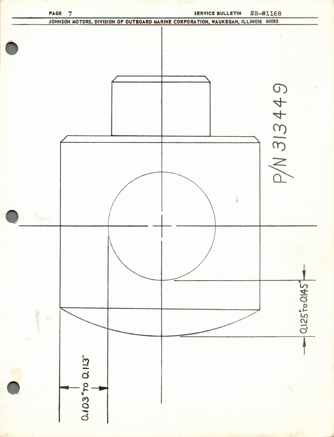
d. P/N 313449 Clutch Pin Retainer-hole off location (Fig. 6).
4. ENGINE WILL NOT SHIFT INTO REVERSE UNDER ANY CIRCUMSTANCE.
Possible causes:
a. No electrical power to reverse solenoid (blue wire), or neutral solenoid (green wire).
b. Defective reverse solenoid.
c. Defective (low pressure) pump.
d. Badly worn clutch dog and/or gear driving lugs.
e. Defective shift switch.
5. THE ENGINE WILL SHIFT INTO REVERSE, BUT WILL NOT HOLD IN REVERSE.
Possible causes:
a. Worn clutch dog and/or gear driving lugs.
b. Defective pump assembly.
6. THE ENGINE WILL NOT HOLD IN FORWARD.
Possible causes:
a. Dog clutch assembled onto prop shaft backwards.
b. Worn clutch dogs and/or gear driving lugs.
7. WHEN SHIFTING INTO NEUTRAL, THE ENGINE WILL INTERMITTENTLY HIT FORWARD GEAR. THIS IS PARTICULARLY NOTICEABLE AT LOWER SPEEDS AND BECOMES LESS NOTICEABLE, OR DISAPPEARS COMPLETELY AT HIGHER SPEEDS. ALSO, IT OCCURS MORE FREQUENTLY AFTER THE ENGINE HAS BEEN RUN FOR A WHILE, PARTICULARLY AT HIGH SPEED, THUS HEATING UP THE GEARCASE OIL.
Possible causes:
a. Clutch pin retainer hole off location (Fig. 6).
b. Defective valve housing.
PAGE 6 SERVICE BULLETIN SB-1168
8. THE ENGINE REMAINS IN REVERSE AFTER THE SHIFT CONTROL HAS BEEN PLACED INTO NEUTRAL OR FORWARD.
Possible defects:
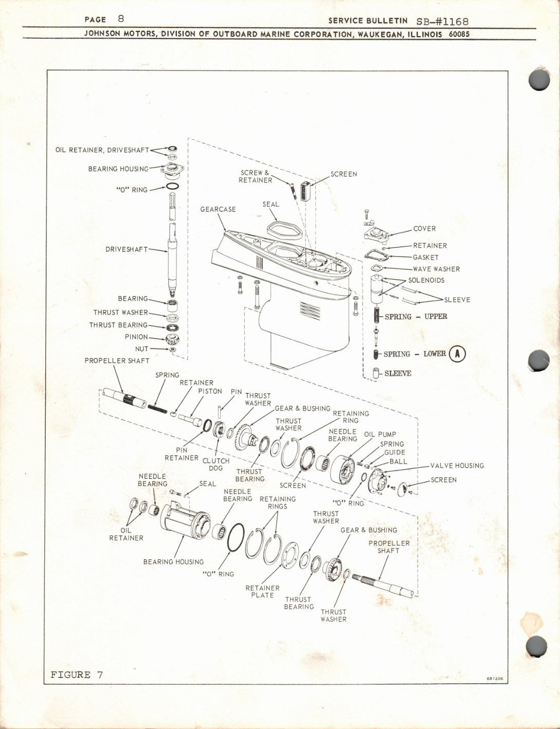
a. Absence of Lower Solenoid Spring, P/N 510800, on shift valve. (Note Fig. 7, letter A)
b. Step in lower end of shift valve bore of valve housing.
c. Nicks or burrs in shift valve bore of valve housing.
d. Entrapped chips between shift valve and valve housing.
e. Clutch pin retainer hole off location (Fig. 6).
NOTE: For your convenience, an exploded view of the Hydro-Electric shift gearcase is illustrated in Figure 7.
JOHNSON MOTORS
Carl Klawonn
Administrative Assistant
CK/rkm