Johnson Service Bulletin SB-994 - Powerhead Removal and Installation

December 2, 1963. Factory instructions for 1964 3 HP JW and JH engines, with original illustrations and cooling-system checks.

Johnson Motors gray Service Bulletin letterhead
SB-#994
File after SB-993
December 2, 1963
SUBJECT: Powerhead Removal and Installation
On Engines: 1964 - 3 HP, Models JW and JH
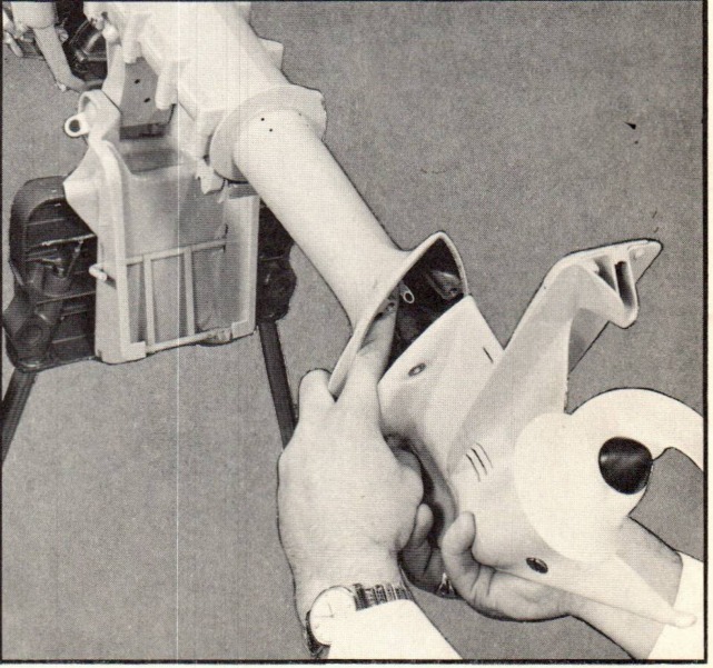
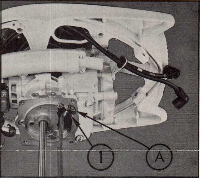
The upper end of the water tube has been anchored to the powerhead adaptor plate by means of a rubber grommet on all 1964 - 3 HP engines. (See Figure 1).
Removal of the powerhead from these engines usually results in the water tube being separated from its connection in the pump housing. Before the powerhead can be re- installed, the gearcase must be removed since it is impossible to guide the water tube back into the pump housing from the top end of the exhaust tube. Once the powerhead has been installed, however, the water tube can be guided into the pump housing from the gearcase end. (See Figure 2).
Exercise caution when installing the powerhead to the exhaust tube; make certain there is adequate clearance between the opening in the water tube and the wall of the adaptor plate for unrestricted water flow. (See Arrow A, Figure 1). Note that the water tube is bellmouthed at its top opening to prevent it from slipping out of the rubber grommet.
CHECK OPERATION COOLING SYSTEM
One can tell immediately if the cooling system is operating properly on most engines, by watching for water discharge at the exhaust relief opening after starting the engine. Due to the design of the new strengthened exhaust tube which is employed on all 1964 - 3 HP engines, it is impossible to detect water discharge at the exhaust relief opening until the engine is turning at least 1000 RPM (throttle quadrant approximately in start position).
Johnson factory figure-1
Figure 1.
Johnson factory figure-2
Figure 2.
PAGE 2 SERVICE BULLETIN
JOHNSON MOTORS, DIVISION OF OUTBOARD MARINE CORPORATION, WAUKEGAN, ILLINOIS 60086
Check for operation of the cooling system on these engines by placing a cupped hand below the exhaust relief openings after motor speed has been advanced to 1000 RPM. Water spray should be noticeable from the exhaust relief openings at this time.
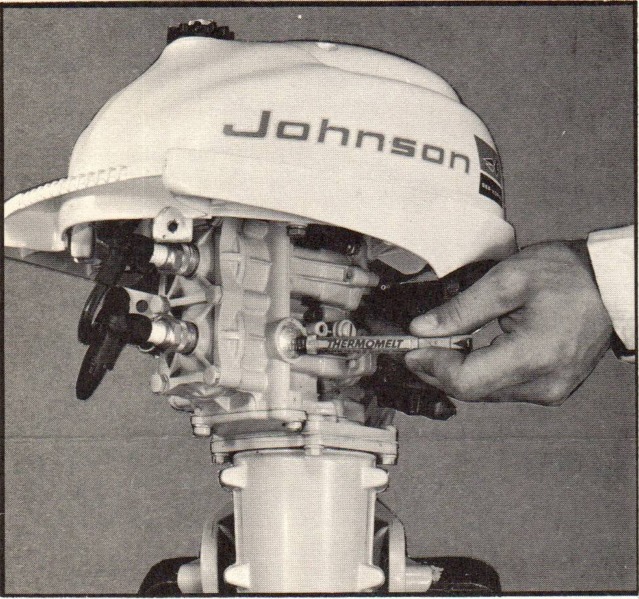
A more accurate means of checking cooling system operation on these engines is with a 165 degree FAHRENHEIT THERMOMELT STIK. Place this stick against the side of the cylinder (preferably on the serial plug) after engine has reached operating tempera- ture. This stick should not melt. Do not use the stick on the cylinder head, how- ever, since the center of the head on these engines will run slightly hotter than 165 degrees FAHRENHEIT.
This engine does not have a thermostat so do not be alarmed it will not melt a 125 degree FAHRENHEIT THERMOMELT STIK.
Johnson factory figure-3Johnson factory figure-4
Figure 3
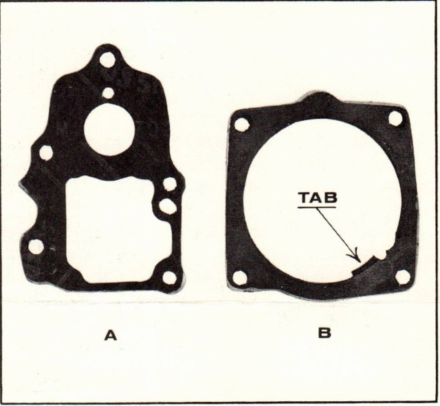
Figure 4
REPLACING GASKET
Always replace the gasket between the adaptor and exhaust housing when installing a powerhead - (Item A, Figure 4). Also, replace the gasket between the cylinder and adaptor plate whenever the adaptor plate is removed from the cylinder during motor repairs - (See Item B, Figure 4).
Sincerely, JOHNSON MOTORS Robert Compton Administrative Assistant
RC:eb
NOTE: Post on your 3 HP, JW, JH index under the heading "POWERHEAD".