POWERHEAD #1002
January, 1973
DEFECTIVE CYLINDER TO CRANKCASE BOLTS 1973 85, 115, 135
NOTE
We recently learned that some 1973 Evinrude 85, 115 and 135 HP engines may have been assembled with defective crankcase to cylinder bolts. The bolts in question (P/N 317926) are the upper two. The engines in question fall within the following serial number blocks:
| 85393 | From 01726 | Through 02950 |
| 115393 | From 01651 | Through 03175 |
| 135383 | From 01751 | Through 03300 |
Several weeks ago, we contacted those dealers who originally bought these engines advising them of the problem and how to fix it. However, since it is possible that some of these engines are no longer in the selling dealer's territory, the bolts may not have been replaced.
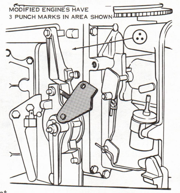
If any engine within the serial number block listed above is brought into your shop for service, please check to determine if the bolts have been replaced. All engines which have had the bolts replaced can be identified by three punch marks in the area shown.
NOTE
It is vital that every engine within the serial number blocks listed be modified since a defective bolt may break resulting in extensive damage to the powerhead.
If you find an engine which has not had the bolts replaced, order a modification kit (P/N 279648) from the Evinrude Service Department. The kit includes detailed installation instructions as per the enclosed sheet and a return mailing bag for the defective screws. Place the defective screws in the mailing bag, fill in the required information on the tag attached to the bag, and mail the bag and screws to the Evinrude Service Department.
IMPORTANT - Use one bag for each engine modified. Do not enclose the screws from more than one engine in a bag. The completed tag on the mailing bag is your claim for labor reimbursement; make sure it is legible. Upon receipt of the mailing bag and original screws, a $10.00 labor check (for each engine modified) will be forwarded to you.
EVINRUDE MOTORS
Service Department
INSTRUCTION SHEET POWERHEAD #1002 (2)
NOTE
Disconnect battery cables from battery before working on engine.
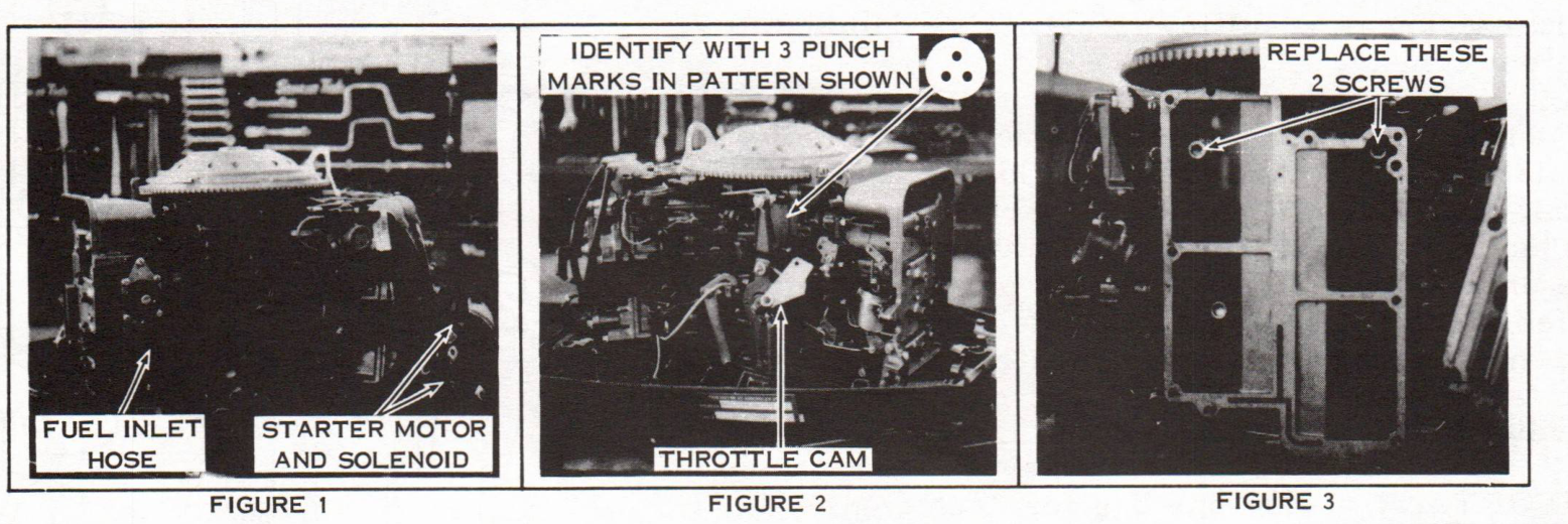
1. Remove screws securing starter motor and starter solenoid to engine. Move starter and solenoid to rear of engine and lay on lower motor cover. See figure 1.
2. Disconnect corbin clamp securing fuel inlet hose to filter cap. Remove hose from cap.
3. Snap choke knob rod out of retainer on lower carburetor.
4. Remove carburetor air silencer cover.
5. Remove shoulder screw securing throttle cam to intake manifold. Move throttle cam away from engine. See figure 2.
6. Remove throttle and shift control cables from engine.
7. Remove 10 screws securing intake manifold to crankcase. (The top center screw can be removed quickly by using a 1/4” drive 5/16” universal joint socket, extension and ratchet and reaching the screw through the air intake opening of the air silencer base.)
8. Carefully separate manifold and carburetor assembly from crankcase and lay manifold and carburetor assembly to port side of engine. Remove and discard manifold gasket (P/N 316129). Be careful not to damage leaf plates or gasket surfaces.
9. Remove upper two crankcase to cylinder screws. See figure 3.
10. Coat threads of new screws supplied with OMC Gasket Sealing Compound (P/N 317201) and install in crankcase. Torque both screws to 18-20 foot pounds.
11. Place new gasket supplied on intake manifold and assemble to crankcase. (To insure wrench clearance, tighten the top starboard manifold to crankcase screw first.)
12. Reinstall throttle cam.
13. Coat threads of starter attaching bolts with Gasilia (P/N 200763) and install starter motor. The bolt running through single tab should be tightened first with bolts in remaining two tabs tightened last.
14. Reinstall starter solenoid, carburetor air silencer cover, choke knob rod, and fuel hose.
15. Synchronize the carburetor and distributor linkage as explained on page 4-14 of the 1973 85, 115 or 135 HP Service Manual.
16. Connect throttle and shift control cables readjusting if necessary.
17. Identify engine as having been updated by making three punch marks in a triangular pattern at point shown in figure 2.
18. Put screws removed from crankcase into mailing bag supplied. Fill in information required on tag and return screws to factory.