POWERHEAD #1003 PG. (2)
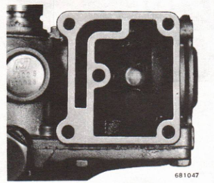
b. Remove exhaust cover and gasket by removing the cover plate screws. See Figures 5-5 & 5-4.
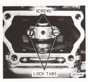
c. Straighten out the lock plate tabs which are bent up against the connecting rod cap screws. NOTE: If tabs are broken off it is very important that they are found so that in reassembly they do not remain in the engine. Remove the connecting rod cap screws. See Figure 5-6.
d. Remove connecting rod cap and 30 needle bearings. Avoid loss of needle rollers or connecting rod top cap dowels.
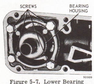
e. Remove four screws and lower main bearing and seal housing. See Figure 5-7. The lower main bearing and seal are not serviced separately. If bearing or seal are damaged, entire assembly must be replaced.
f. Remove crankshaft through bottom of crankcase.
g. Reinstall rod cap on rod. See Figure 5-16. Push piston through cylinder until piston rings are exposed. Remove piston rings. Remove piston and rod through front of crankcase. DO NOT try to save the rings. Install a set of new rings on every power head service job.
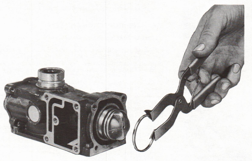
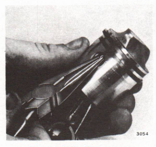
h. If necessary to remove piston from connecting rod, remove wrist pin retaining rings, using needle-nose pliers. See Figure 5-8. Drive wrist pin through to free piston from connecting rod. See Figure 5-9.
NOTE One side of piston is marked “L” on inside. When wrist pin is to be removed, “L” side of piston must be up and driving tool must be applied to loose end. Be careful not to distort piston. See Figure 5-10.
i. Upper main bearing and seal can be removed by supporting crankcase properly and pushing out with a suitable tool.
CLEANING, INSPECTION AND REPAIR
CYLINDER BLOCK AND CRANKCASE
Check cylinder wall for excessive wear and check cylinder port for carbon accumulation. Cylinder wall wears in various degrees depending on lubrication and conditions under which the motor is operated. Major portion of wear is in the port area and the area covered by ring travel.
Check cylinder for size and wall straightness by using an inside micrometer or dial bore indicator. Refer to Section 2 for specified dimensions. If wear is greater than .002”, replace cylinder block or rebore block for oversize pistons. Piston and ring sets are available .030” oversize. NOTE: If your shop is not equipped to rebore cylinder blocks, write the Service Department about our reboring service.
Carbon accumulation in the exhaust ports restrict the flow of exhaust gases and has considerable effect on performance of the motor. Carefully scrape carbon from cylinder head and exhaust ports with scraper or other blunt instrument. Exhaust ports and all exhaust passages must be free from carbon deposits to insure maximum performance.
With continued operation of the motor, the cylinder wall will take on a glaze which reduces the effectiveness of the seal between the piston rings and the cylinder wall. The result will be reduced compression and a decrease in performance of the engine. Before reinstalling the