
February, 1972
SUBJECT: Pulse Pack and Rotor Assembly P/N 385036
Installation 1968, 100 H.P. Models V4T-V4TL-14
When installing the subject pulse pack and rotor assembly, it is important that the electrical system be rewired in accordance with the instruction sheet provided. (See over for instruction sheet copy.)
When rewiring as instructed the ignition system is isolated from the charging circuit, eliminating possible engine misfire.
Inadvertently the 19' of 12 Ga red wire and 5/16" ring terminal were left out of the subject pulse pack and rotor assemblies packaged and shipped to date. It will be of necessity that these two items be obtained by you from your available source so that proper installation can be made.
J. R. Penland
Service Promotion Manager
JP/sn
NOTE: Post on your 100 H.P. index under the heading "Ignition".
PULSE PACK AND ROTOR ASSEMBLY
PART NO. 385036
DISCONNECT BATTERY
For proper pulse pack operation, discard old sensor rotor, then install new rotor and pulse pack.
Pulse pack leads color coded: blue leads - sensor; green lead - pulse transformer plus side (+); black
lead - pulse transformer negative side (-); red lead - to voltage suppressor; short black lead - ground to pulse pack through mounting screw.
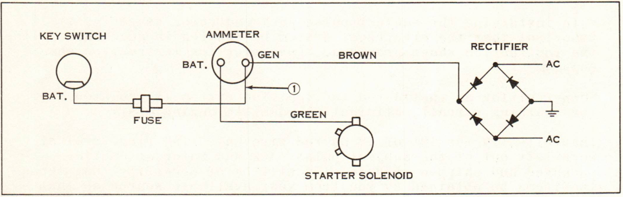
Rewire electrical system as shown under NEW WIRING.
ORIGINAL WIRING
NEW WIRING
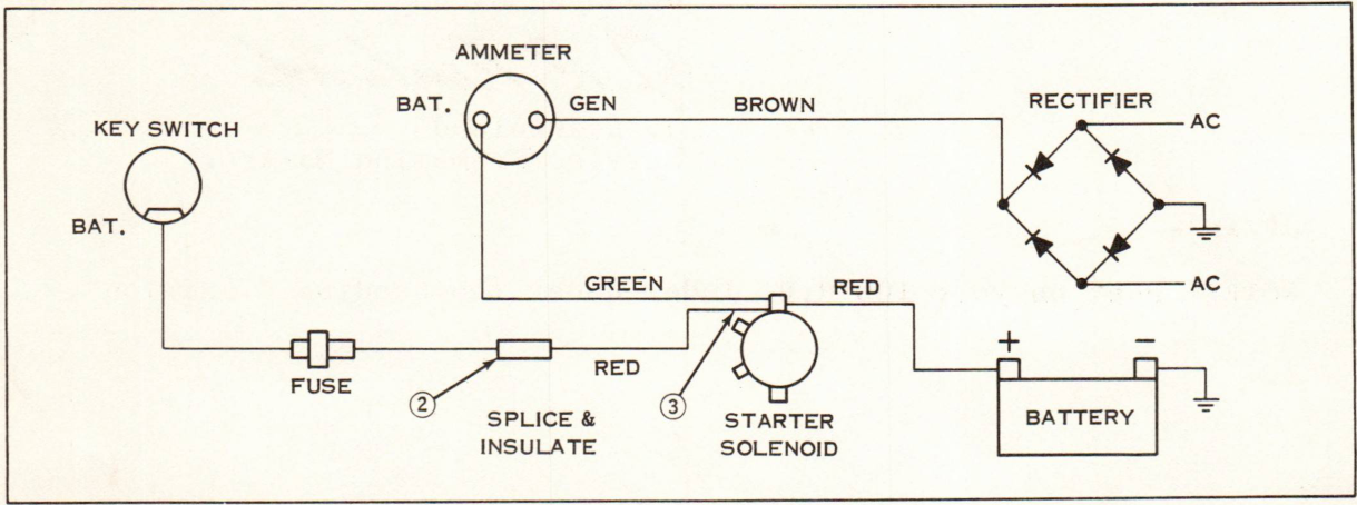
① Remove fuse lead (key switch to ammeter) from the GEN side of the ammeter.
② Splice in 12 GA red lead furnished in kit (from fuse to solenoid as shown in new wiring) by removing ring terminal from fuse lead, stripping off insulation about 1/2" back and twisting leads together.
Solder the connection and insulate.
③ Install 5/16" ring terminal to opposite end of red lead, solder, and connect the ring terminal to starter solenoid as shown.
RECONNECT BATTERY