Johnson Service Bulletin SB-1306 - Shift & Throttle Cable Adjustment
This 1973 Johnson factory bulletin explains the correct installation and adjustment of shift and throttle cables on 50 through 135 H.P. remote-control outboards, including cable overtravel, shift engagement, and idle-return checks.
SB-#1306
SUBJECT: Shift & Throttle Cable Adjustment
ON MODELS: 1973 - 50 through 135 H.P. Remote Control
Correct installation and adjustment of the shift and throttle cables at the engine
is extremely important for satisfactory control operation. Incorrect adjustment
can result in inconsistent idle speed and/or hard shifting; and in extreme cases
cause permanent damage to the remote control, engine linkage and gearcase.
The remote control installation instructions (copy attached) provide a step-by-
step procedure for making a correct control installation. Most of the procedure
is similar to what you have done to install controls prior to 1973 models;
however, some items are different from or in addition to what you are used to.
The most important of these are listed here for emphasis.
1. Use only the attaching screws, nuts and washers supplied with the
remote control. Each piece has been selected to meet specific
requirements; substitutes may interfere with adjacent parts or
come loose during operation.
2. Since there are two cables, be sure they are not interchanged at
the engine. The throttle cable can be easily identified by
moving the warm-up lever while observing the two cable ends.
When the warm-up lever is moved, the throttle cable end will move.
Forcibly moving the control lever with the cables interchanged
at the engine will damage the control.
3. This is a mechanically shifted gearcase, and as such the propeller
shaft must be rotated when shifting to insure full clutch dog
movement. Failure to rotate the propeller shaft while shifting
can cause improper shift cable adjustment and damage to the remote
control and engine linkage.
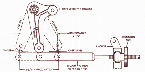
The shift cable travel must be centered on the engine shift lever
travel. See Figure 14 & 15 and pages 5 & 6 of the installation
instructions, and the illustrated instructions listed on the next
page.
The idea is to center the approximately 2 5/8" travel of the shift cable with the
2½" travel of the motor shift lever. The cable overtravel compensates for back-
lash in the system.
(1)
PAGE 2 SERVICE BULLETIN SB-#1306
JOHNSON OUTBOARDS, DIVISION OF OUTBOARD MARINE CORPORATION, WAUKEGAN, ILLINOIS 60085
JOHNSON OUTBOARDS, DIVISION OF OUTBOARD MARINE CORPORATION, WAUKEGAN, ILLINOIS 60085
A. Make this adjustment before the cable is attached to the engine
shift lever.
B. Put remote control in full forward and put motor shift lever
firmly into forward gear (turn prop shaft by hand to be sure
clutch dog is fully engaged and not "butting"). Adjust
trunnion nut to give cable approximately 1/16" overtravel.
C. Move control lever and motor shift lever fully into reverse
and note under or overtravel.
D. Alternating between forward and reverse, adjust trunnion nut until
cable overtravel is the same at both ends of the motion.
E. Connect cable end to shift lever.
4. The throttle cable must be adjusted just tight enough to insure that the engine
throttle lever returns to its idle stop. If this cable is too loose, the engine
idle speed will be high and inconsistent, causing difficulty shifting out of
gear. If it is too tight, the control will feel stiff through the shifting
range, and the warm-up lever will tend to move up when shifting to neutral.
To insure satisfactory operation of this new remote control, be certain your service
personnel read and understand the installation instructions, paying particular
attention to the items above.
JOHNSON OUTBOARDS
Doug Cankar
Technical Data Coordinator
DC/sn
NOTE: Post on your 50 through 135 H.P. under the heading "Miscellaneous".
Historical notes
The factory emphasizes rotating the propeller shaft when shifting to ensure complete clutch-dog engagement. The diagram and dimensions are reproduced from the original publication.