Johnson Service Bulletin SB-1363 - Trim and Tilt Unit Service Tips
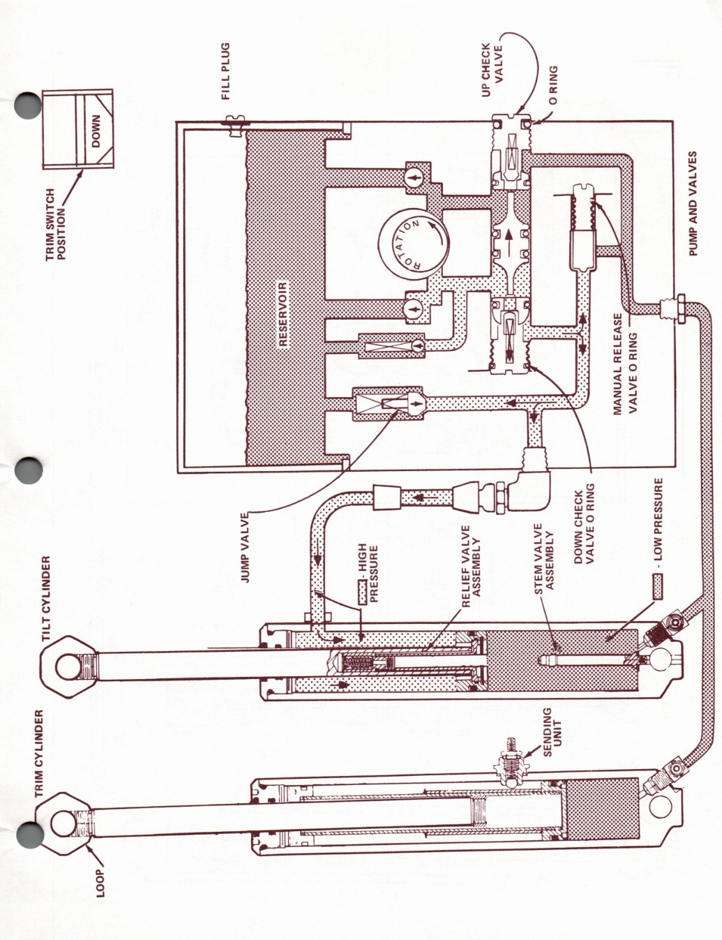
Issued April 1975 for 50 through 135 H.P. models equipped with Calco trim-and-tilt units. Nine factory pages cover trim gauge, electrical and hydraulic troubleshooting, including wiring and hydraulic circuit schematics.
Factory pages are reproduced as high-resolution images to protect the original technical diagrams and layout. Expand the searchable transcript beneath each page to find and copy its text. OCR transcripts may contain recognition errors; consult the factory page image for exact specifications.

SB-#1363
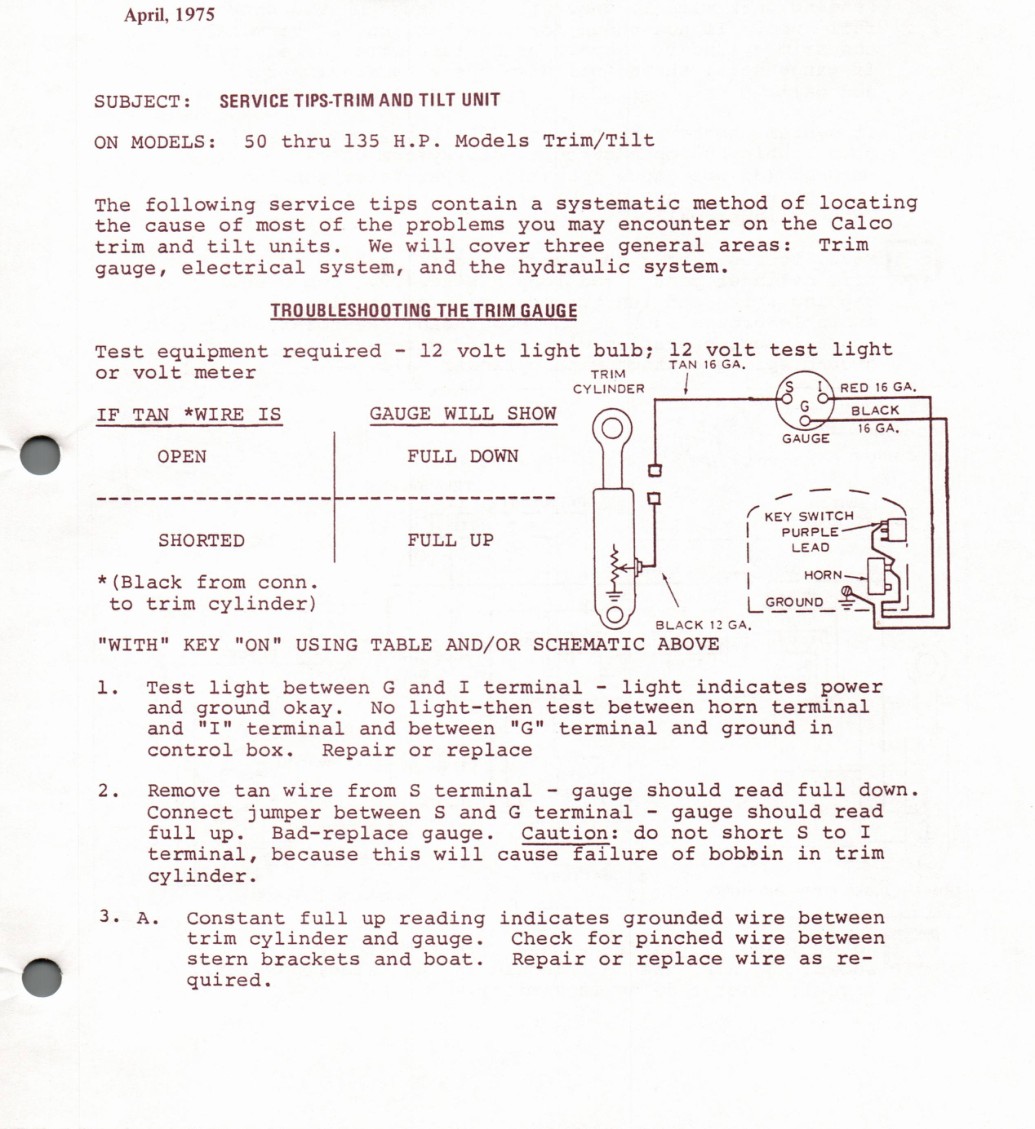
Searchable text - factory page 1
MM
SERVICE BULLETIN Jengson..
EY PARTS MGR.
WAUKEGAN ILLINOIS 60085 SB-1363
SERVICE MGR.
1975 April,
UNIT TIPS-TRIM AND TILT SERVICE SUBJECT:
Trim/Tilt Models thru 135 H.P. MODELS: 50 ON
locating systematic method of service tips contain following The a
the Calco of of the problems encounter the most may on cause you
Trim units. will three general trim and tilt We areas: cover
hydraulic electrical and the system. system, gauge,
TROUBLESHOOTING THE GAUGE TRIM
light 12 volt equipment required 12 volt light bulb; test Test - GA, TAN 16 volt meter or Thi | GA. RED 15 cyuinoer
*WIRE GAUGE WILL SHOW IF TAN IS
0
DOWN OPEN FULL
eae Bem Q anaes eS EE oer at ees ( SWITCH KEY
PURPLE FULL UP SHORTED | LEAD
} D HORN | \ * (Black from conn.
trim cylinder) Lemus to
BLACK 12 GA,
AND/OR "WITH" "ON" ABOVE KEY USING TABLE SCHEMATIC
light indicates 1. light and terminal Test between G I power -
terminal and light-then between horn ground okay. No test
"I" "G" terminal and ground in and terminal and between
Repair replace control box. or
should full down. 2. wire from terminal read Remove S tan gauge -
jumper terminal should read between and G Connect S gauge -
full Caution: do short I Bad-replace not S to gauge. up.
failure bobbin trim terminal, this will of in because cause
cylinder.
3. wire full reading indicates grounded between A. Constant up
pinched wire between trim cylinder and Check for gauge.
Repair replace wire brackets and boat. stern Oo as re- or
quired.
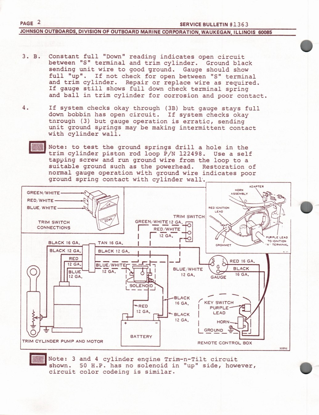
Searchable text - factory page 2
2 PAGE #1363 SERVICE BULLETIN
JOHNSON OUTBOARDS, DIVISION OF OUTBOARD MARINE CORPORATION, WAUKEGAN, ILLINOIS 60085
3. full "Down" B. Constant reading indicates circuit open
"S" terminal between and trim cylinder. Ground black
sending unit wire to good ground. should Gauge show
full "up". If not check for between "S" terminal open
trim and cylinder. Repair replace wire required. or as
If still shows full down check terminal spring gauge
and ball in trim cylinder for corrosion and contact. poor
4. If checks okay through (3B) system but full stays gauge
bobbin down has circuit. If checks okay system open
(3) but tnrough operation is erratic, sending gauge
unit springs ground be making intermittent contact may
with cylinder wall.
[Ba
vcee: the ground springs drill to test hole in the a
trim cylinder piston P/N rod loop 122498. self Use a
tapping wire and ground from the loop screw to run a
suitable ground such the powerhead. Restoration of as
normal operation with wire ground indicates gauge poor
ground spring with cylinder contact wall.
AOapreR
GREEN/WHITE
RED, WHITE Y
| BLUE, WHITE neo tonirion
TRIM SWITCH] \ GREEN, WHITE 12 GA, | TRIM SWITCH
CONNECTIONS REO
[oe | Pumps Leso A° TERNAL 2 BLACK 16 GA, TAN 16 GA, i
BLACK 12 GA. BLACK 12 GA, H :
RED 4 St ee 12 GA, BLE waite
oRepren of Ns ica BLUE
| 12 GA, %
I
Leena ENOID a
a BLACK
KEY SWITCH 16 GA, | RED PurPLE
pena | LEAD siack h 126A. | HORN. 2 -
GRO UNE | =
BATTERY
TRIM CYLINDER PUMP AND MOTOR REMOTE CONTROL BOX
[Ea rete:
3 and 4 cylinder engine Trim-n-Tilt circuit
c ) "up" shown. 50 has solenoid in side, however, H.P. no
circuit color codeing is similar.
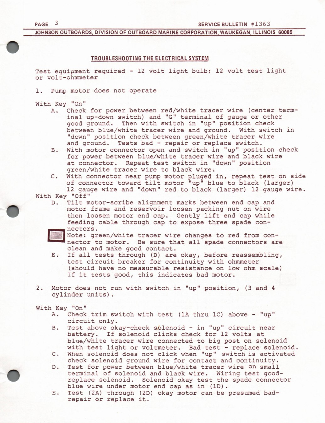
Searchable text - factory page 3
3 #1363 SERVICE BULLETIN PAGE
ILLINOIS 60085 JOHNSON OUTBOARDS, DIVISION OF OUTBOARD MARINE CORPORATION, WAUKEGAN,
LESH ELECTRICAL SY‘ HE
light light 12 volt required 12 volt bulb; test equipment Test -
volt-cohmmeter or
does 1. not operate Pump motor
"On" With Key
wire (center for between red/white Check tracer term- A. power
other inal switch) and "G" terminal of up-down or gauge
with switch in "up" position check good ground. Then
blue/white With switch in wire ground. between tracer and
wire "down" position check between green/white tracer
bad repair replace switch. and ground. Tests or -
in "up" position check With and switch motor connector B. open
blue/white wire wire between and black for tracer power
switch in "down" position connector. Repeat test at
green/white wire wire. black tracer to
side With in, C. pluged connector motor repeat test near pump on
(larger) of tilt "up" blue black connector toward to motor
wire. 12 wire and "down" black (larger) 12 red to gauge gauge
With "Off" Key
motor-scribe alignment Tilt marks between end and D. cap
reservoir frame and loosen packing wire nut motor on
lift end while then loosen end Gently motor cap. cap
feeding cable through three spade to expose con- cap
nectors.
green/white wire changes red from Note: tracer to con-
that all spade nector to motor. Be connectors are sure
clean and make good contact.
reassembling, If all through (D) okay, before E. tests are
circuit breaker for continuity with ohmmeter test
scale) (should have measurable resistance low ohm no on
it this If good, indicates bad tests motor.
2. does with switch in "up" position, (3 and 4 Motor not run
cylinder units).
With "on" Key
Check trim switch with (1A 1C) "up" A. thru above test -
circuit only.
"up" circuit above okay-check sOlenoid in B. Test near -
battery. If solenoid clicks check for 12 volts at
blue/white solenoid wire big connected tracer to post on
with light solenoid. voltmeter. Bad replace test test or -
solenoid switch is activated When does click when "up" Cc. not
continuity. check solenoid ground wire for and contact
wire for between blue/white small D. Test tracer on power
terminal of solenoid wire. Wiring good- and black test
replace solenoid. Solenoid okay the spade test connector
blue wire under in (1D). end motor cap as
(2A) E. Test through (2D) okay be presumed bad- motor can
repair replace it. or
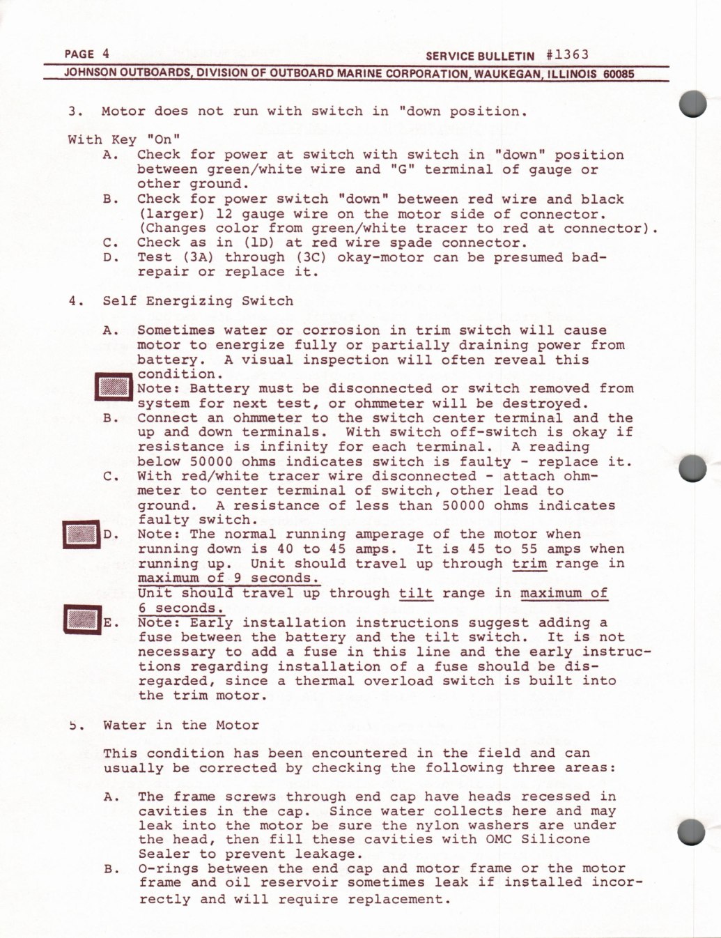
Searchable text - factory page 4
4 PAGE #1363 SERVICE BULLETIN
JOHNSON OUTBOARDS, DIVISION OF OUTBOARD MARINE CORPORATION, WAUKEGAN, ILLINOIS 60085
o)
with switch 3. does in "down position. Motor not run
"On" With Key
Check for switch with switch in "down" position A. at power
green/white between wire and "G" terminal of gauge or
other ground.
Check for switch "down" between red wire B. and black power
(larger) 12 wire side the of motor connector. gauge on
(Changes from green/white color red connector). tracer to at
Check in (1D) wire Cc. red spade at connector. as
(3A) through (3C) Test okay-motor be presumed bad- D. can
repair replace it. or
4. Self Energizing Switch
Sometimes corrosion in trim switch will A. water cause or
energize fully partially draining from motor to or power
battery. visual inspection will this often reveal A
condition. [Eaicce:
disconnected switch from be removed Battery must or
for ohmmeter will be destroyed. system next test, or
ohmmeter the switch terminal and the B. Connect center to an
and down terminals. With switch off-switch is okay if up
resistance is infinity for each terminal. reading A
( } indicates it. below 50000 ohms switch is faulty replace -
With red/white wire disconnected C. attach ohm- tracer -
terminal of switch, other lead meter to center to
resistance indicates ground. of less than 50000 ohms A
faulty switch.
running of Note: The normal the when motor amperage
running down is 40 45 is 45 55 when to It to amps. amps
running in Unit should travel through trim range up. up
maximum of 9 seconds.
should travel through tilt in maximum of Unit up range
6 seconds. a:.
installation instructions adding Early Note: suggest a
fuse battery tilt switch. is between the and the It not
add fuse in this line early instruc- and the to necessary a
tions installation dis- regarding of fuse should be a
into regarded, since switch is built thermal overload a
the trim motor.
in the Water Motor 5.
This condition has been encountered in the field and can
checking the following three usually be corrected by areas:
frame have heads recessed in The through end A. screws cap
cavities in Since collects here and the water may cap. [ ) under leak into the be the nylon washers motor are sure
cavities with Silicone the head, then fill these OMC
Sealer leakage. to prevent
O-rings frame between the end and the B. motor motor cap or
frame oil reservoir sometimes leak if installed incor- and
rectly and will require replacement.
Searchable text - factory page 5
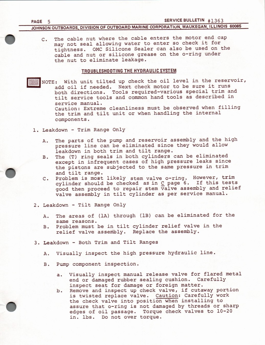
BULLETIN SERVICE 41363 PAGE 5
60085, ILLINOIS WAUKEGAN, MARINE CORPORATION, OUTBOARD DIVISION OF OUTBOARDS, JOHNSON
‘.) end the motor cable enters cap where the cable nut The Cc. it for check allowing to enter seal water so not may the used also be Sealer Silicone on OMC can tightness.
o-ring under the silicone and cable nut grease on or
leakage. eliminate the to nut
SYSTEM THE HYDRAULIC TROUBLESHOOTING
reservoir, oil level in the check the unit tilted With (OTE: up
it be check motor to runs oil if needed. Next sure add
and special trim required-various directions. Tools both
in described hand tools and service tools tilt as common
manual. service
filling observed when be cleanliness must Caution: Extreme
internal handling the unit tilt when trim and the or
components.
Only Trim Leakdown Range 1. -
high and the reservoir assembly and of the The parts pump A.
would allow since they eliminated line be pressure can
trim tilt in both and leakdown range.
eliminated be cylinders in both (T) ring seals The can B.
since high leaks of infrequent in pressure except cases
in trim subjected the pistons to the same pressure are a tilt and range.
trim likely o-ring. However, is Problem most valve stem C.
this 6. If tests in checked C cylinder should be as page
relief assembly and repair valve proceed stem good then to
service manual. in tilt cylinder assembly valve as per
Tilt Only 2. Leakdown Range -
eliminated for the through (1B) be of (1A) The A. can areas
same reasons.
in the relief valve in tilt cylinder be Problem must B.
assembly. Replace the assembly. relief valve
Tilt Trim and Ranges Both 3. Leakdown -
line. hydraulic high inspect the Visually A. pressure
inspection. Pump component B.
flared metal valve for manual release Visually inspect a.
Carefully sealing cushion. rubber end damaged or
foreign inspect for damage matter. seat or
portion if check valve, cutaway and inspect b. Remove up
work Caution: Carefully is twisted replace valve.
installing into position when to the check valve a]
sharp by threads o-ring is damaged that not or assure
10-20 check valves to of oil edges Torque passage.
in. lbs. torque. Do not over
Searchable text - factory page 6
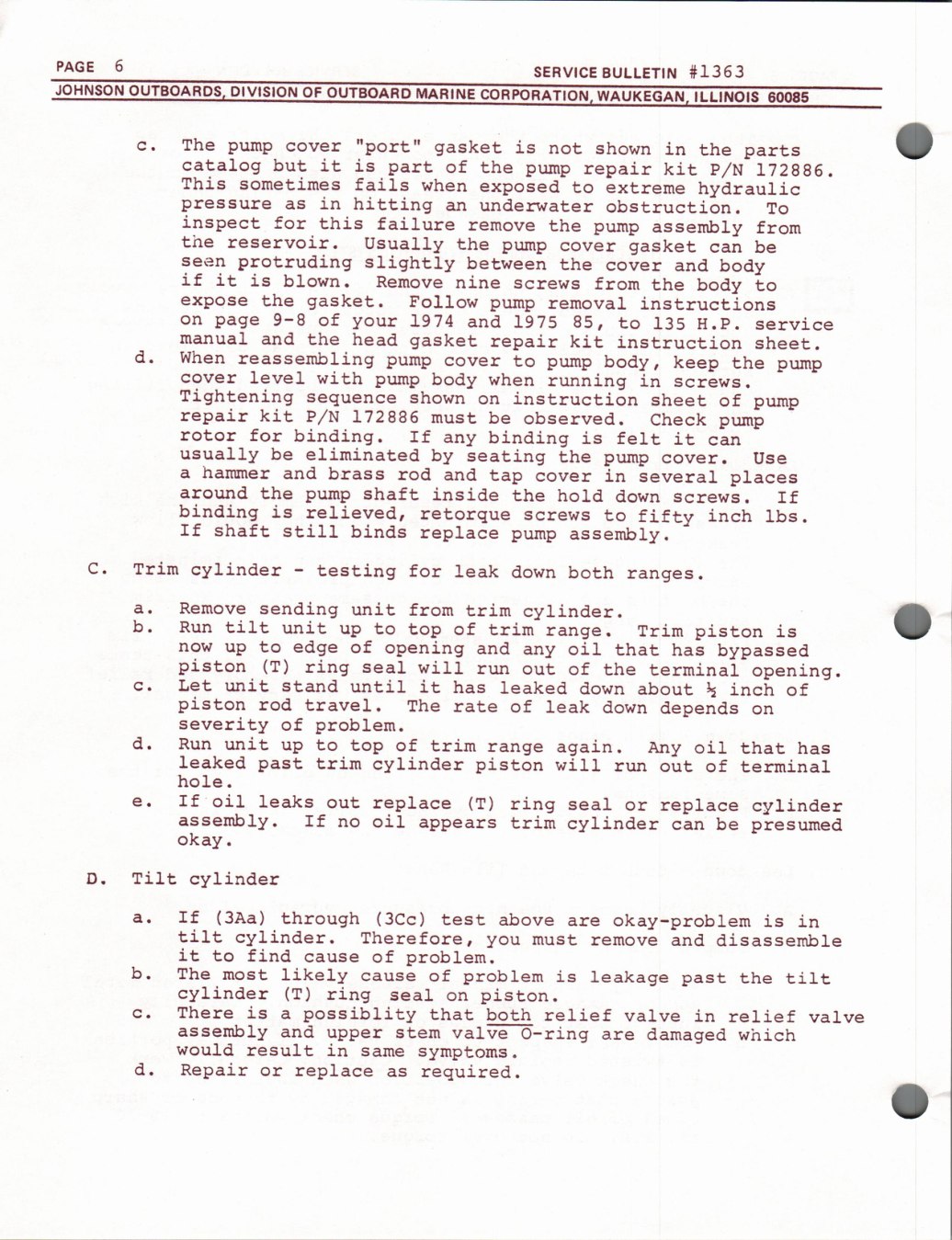
6 PAGE #1363 SERVICE BULLETIN
JOHNSON OUTBOARDS, DIVISION OF OUTBOARD MARINE CORPORATION, WAUKEGAN, ILLINOIS 60085
Vv
The "port" is gasket c. pump shown in cover not the Parts
catalog it but is of part the repair kit P/N 172886. pump
This sometimes fails when exposed to hydraulic extreme
in hitting underwater pressure obstruction. as an To
inspect for this failure the assembly from remove pump
the reservoir. Usually the gasket be pump cover can
protruding slightly between seen the and body cover
if it is blown. nine Remove from the body screws to
the gasket. Follow expose removal instructions pump
9-8 of 1974 on and 1975 85, page 135 your to service H.P.
manual and the head gasket repair kit instruction sheet.
d. When reassembling body, pump to keep the cover pump pump level with body cover when running in pump screws.
Tightening pump shown instruction sequence sheet of on
repair kit P/N pump 172886 be must observed. Check
for binding. rotor If binding is felt it any can
usually be eliminated by seating the Use pump cover.
hammer and brass rod and a in tap several places cover
around the shaft inside the hold pump down If screws.
binding is relieved, retorque inch to fifty lbs. screws
If shaft still binds replace assembly. pump
Trim C. cylinder testing for leak down both - ranges.
VU Remove sending unit from trim cylinder. a.
b. tilt unit Run to of trim top Trim piston is up range.
to edge of opening and oil now that up has bypassed any
piston (T) ring seal will of the terminal out opening. run
unit Let stand until it has leaked c. down about } inch of
piston rod travel. The of rate leak down depends on
severity of problem.
d. unit Run to of trim top again. oil that up Any has range
leaked trim cylinder past piston will of terminal out run
hole.
If oil leaks replace (T) e. out ring seal replace cylinder or
assembly. If oil trim cylinder be no presumed appears can
okay.
Tilt cylinder D.
(3Aa) If through (3Cc) above a. test okay-problem is in are
tilt cylinder. Therefore, disassemble must and you remove
it find to of problem. cause
b. The likely most of problem is leakage the tilt cause past
cylinder (T) ring piston. seal on
There is possiblity that both relief c. valve in relief a valve
assembly and stem valve O-ring damaged upper which are
would result in symptoms. same
d. Repair replace required. or as
Searchable text - factory page 7
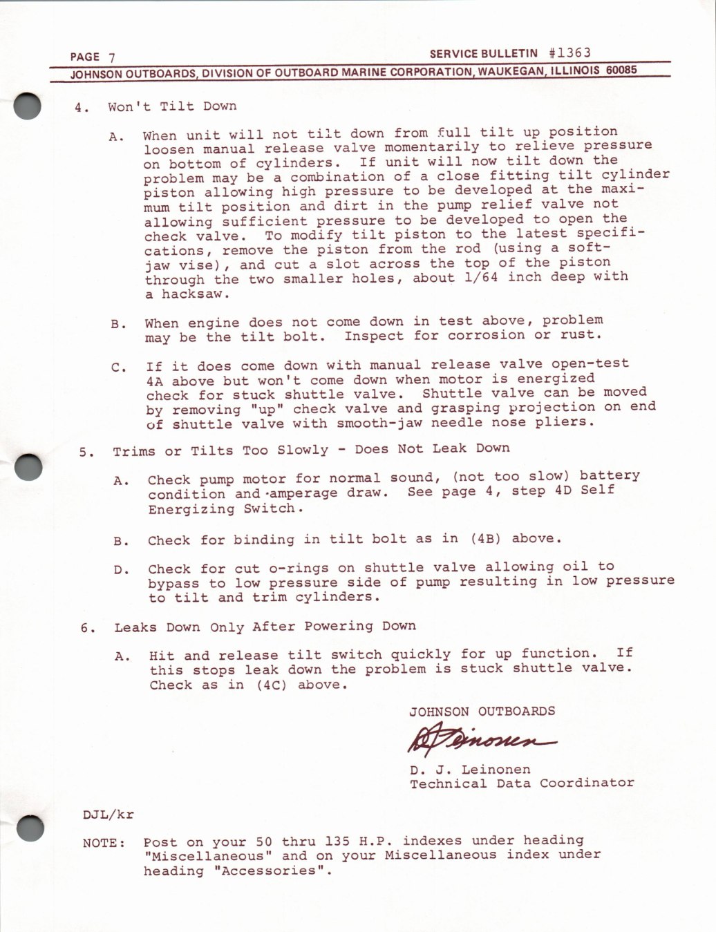
#1363 SERVICE BULLETIN PAGE 7
60085 ILLINOIS WAUKEGAN, CORPORATION, MARINE OF OUTBOARD OUTBOARDS, DIVISION JOHNSON
e.
Won't Tilt Down
position tilt full from tilt down will up unit not When A. relieve momentarily to pressure valve release manual loosen
the tilt down unit will If cylinders. of now bottom on cylinder tilt fitting of close combination be problem a a may maxi- the developed be at high allowing to piston pressure
relief valve not in the dirt position and tilt pump mum the developed be to open allowing sufficient to pressure
specifi- latest piston the modify tilt to valve. To check
soft- (using the rod piston from the cations, a remove
piston of the the slot top vise), and jaw cut across a
with 1/64 inch deep holes, about smaller the through two
hacksaw. a
problem above, in down test engine does not When come
corrosion rust. for tilt bolt. Inspect or be the may
valve open-test manual release with down If it does come
energized is won't when down motor but 4A above come
moved be Shuttle valve shuttle valve. stuck can check for
end projection grasping and "up" check valve on removing by
pliers. smooth-jaw needle with valve of shuttle nose
Leak Down Slowly Not Does Tilts Trims Too or -
battery slow) sound, (not too normal for Check motor A. pump Self 4D 4, step draw. See condition and-amperage page
Switch. Energizing
in tilt bolt (4B) above. binding in for Check as
oil allowing to o-rings shuttle valve for Check cut on
resulting in low side of pressure low bypass to pump pressure
trim cylinders. tilt and to
Powering After Down Leaks Only Down
function. If switch quickly for tilt release Hit and up A.
valve. shuttle is stuck the problem leak down this stops
in Check (4C) above. as
OUTBOARDS JOHNSON
Grincnen—
Leinonen J. D.
Coordinator Technical Data
DJL/kr
heading under 135 indexes 50 thru H.P. Post NOTE: on your
index under Miscellaneous "Miscellaneous" and your on
"Accessories". heading
Searchable text - factory page 8
9nd »93HO BATVA
ONIN
WW
dN
O
Nmoa
S3A1VA
HOLIMS
GNV
NOILISOd
dnd WHHL
3SV3134
ONIY
O TVNNYW
3ATVA
fr
SYNSS3Yd ONIX »193HO
Sa
O AIVA BATVA 3A1VA SATIVA ATawassv NMOG MOT ATawassv HOIH aunssaud
awnr MBONITAD
Was - 431138 EE=, “EE
il
LIL |
&
ONIGNaS M3GNITAD
LINN.
WEL
dooT
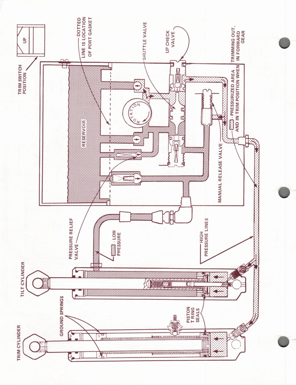
Searchable text - factory page 9
NOILV907 LaASVD g3iLoa
BATVA
“LNO
93H uv: GuVMYOS BATWA
LYOd E}) an ONINWIYL| 31LiNHs4 SI
an 3NIT 40
NI
HOLIMS INS3HM = V3V NOILISOd
NOILISOd WIHL G3ZIuNSSaud
WIH1
NI - Gy) GNY
3ATVA
3SV31ay
TWANVW
ice
431743u S3NI7
Mot HOIH auNSS3ud 3uNSS3ud 3uNssaud
- eae
YBQNITAD
LIL
ce SONIHdS
NOLSId ONIY sivas
GNNOYD
L
YIGNITAD
WINE ba
Archive notes
The original bulletin includes troubleshooting guidance for trim gauge readings, pump motor electrical circuits, hydraulic leakdown, valves and cylinders. Pages 8 and 9 contain the hydraulic DOWN and UP circuit drawings.