SB-1521 - Correct Installation of OMC Long Life Remote Control Cables
Issued March 1980, this Johnson Service Bulletin explains correct installation of Type “O” remote control cables using adaptor kit P/N 173600. It documents wire clamp positioning, lubrication, torque requirements and safety precautions.

SB-1521
March, 1980
Subject: Correct Installation OMC Long Life™ (Type “O”) Remote Control Cables
Models: OMC Long Life Cable Adaptor Kit, P/N 173600
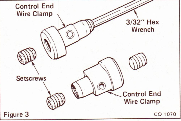
The incorrect installation of casing guides used with OMC Long Life (Type “O”) Remote Control Cables may lead to hard shifting or high throttle effort. The core wire must not protrude from the casing guide but must be flush to 1/32” recessed within the casing guide.
When using OMC Long Life Cable Adaptor Kit, P/N 173600, the following procedures are to be used. They are to be used along with the instructions supplied with your remote control and Adaptor Kit.
Cable Attachment to Remote Control
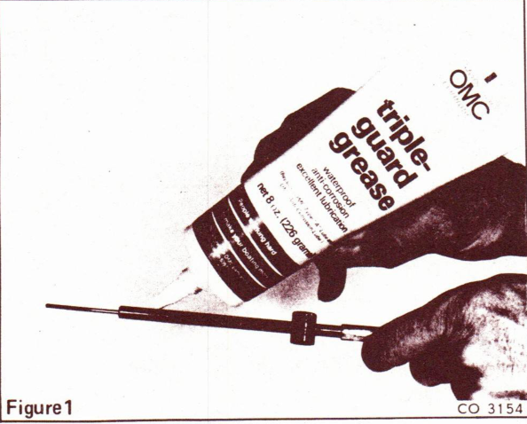
1. Lubricate outside of brass sleeves at control end of both control cables with OMC Triple-Guard Grease. See Figure 1.
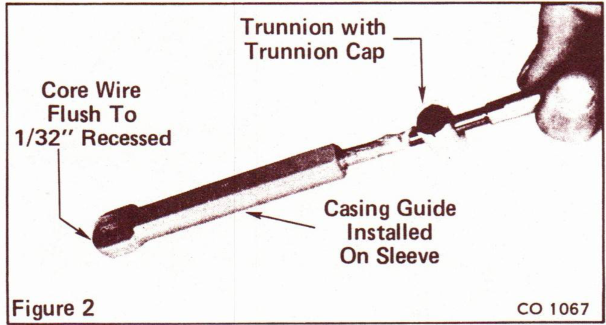
3. Start setscrews into each end of both control end wire clamps. See Figure 3.
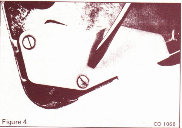
4. With remote controls shipped with outboard motors it will be necessary to remove two screws and plastic plate. See Figure 4. Replace this plate and two screws after cable is installed. Torque screws 10 to 15 in. lbs. (1.2 to 1.6 N·m).
△ Safety Warning
To prevent sudden loss of shift or throttle control, both separator screws must be in place and properly torqued. Excessive torque may break plastic separator plate and allow mechanism to jam.
CR 79-86 © OUTBOARD MARINE CORPORATION 1980
△ Safety Warning
If setscrew is tightened more than one turn the core wire may be weakened and may break. If setscrew is tightened less than one turn, core wire may slip in casing guide. In either case, sudden loss of shift or throttle control may result.
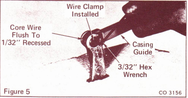
5. Where remote control instructions refer to cable pin, substitute wire clamp and insert it into shift or throttle arm and casing guide. See Figures 3 and 5. Complete these procedures before referring back to remote control instructions.
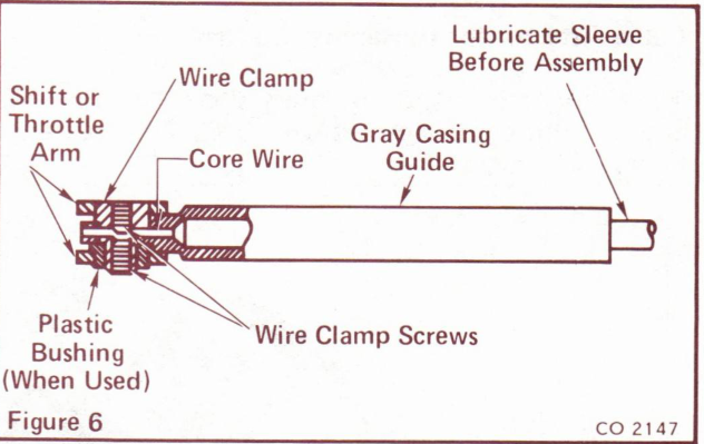
6. Push core wire (from engine end) through wire clamp until core wire is FLUSH TO 1/32” RECESSED IN END OF CASING GUIDE. WIRE MUST NOT PROTRUDE BEYOND END OF CASING GUIDE. Secure wire in clamp as follows:
a. Turn setscrew in on large end of clamp until it touches core wire. Then tighten exactly one more turn, no more and no less.
b. Tighten other setscrew securely. See Figures 5 & 6. (Use setscrew access holes on remote controls shipped with outboards. Position throttle lever by hand to align setscrew with access hole, then punch through red decal with Allen wrench to tighten setscrew.)
JOHNSON OUTBOARDS
D. J. Leinonen
Technical Data Coordinator
NOTE: Post on miscellaneous index under heading “Service Procedure Change.”