OMC Outboard Service Bulletin No. 2101 (1984) addresses improving transducer signal to omc tracker. Transducer signal diagnosis and corrective procedures for OMC Tracker.

OMC Outboard Service Bulletin
Accessories
No. 2101
February, 1984

Subject: Improving Transducer Signal to OMC Tracker™ Models: All transducers used with OMC Tracker Problem: Poor or erratic signals from the transducer

Symptom: Operator observes intermittent or no readings on digital or vertical LCD display.

Causes:

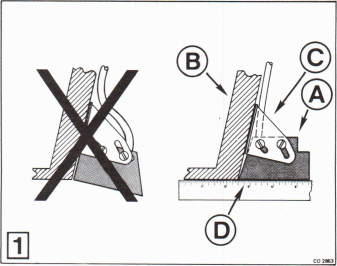
1. Improper transducer mounting - The pictures showing the transducer mounting were incorrect in the original Tracker Owner’s Manual and Installation Instructions. The transducer @ must be mounted with slanted side facing the transom (electrical lead forward). Make sure the transducer is mounted correctly. If not, remove it from the mounting bracket ©) and properly position it on the bracket. The bracket may require vertical adjustment to make transducer bottom face parallel with the boat bottom. Improper location or adjustment of the transducer, or uneven application of RTV Adhesive Sealant between transducer and the transom, will create a disturbance of water flow. A disturbance (air bubbles) will impede the accuracy of the transducer.

2. Transducer dried out - If the boat has been out of the water, the transducer will dry out. This will cause erratic readings for several minutes upon re-entry into the water.

3. Transducer dirty - the bottom face of the transducer is covered with a film of gasoline, oil or marine growth.

4. Transducer painted - the transducer has been painted with unsuitable anti-fouling paint, reducing its sensitivity.

5. Transducer damaged or defective - Poor electrical connections, a defective transducer or a damaged transducer face will cause intermittent or no readings on the Tracker display.
Factory figure 1 for bulletin 2101
1 / 2

2]

Solutions:

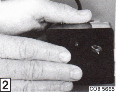
1. MMake sure the transducer is mounted properly. The transducer should be located clear of any obstructions that could cause air bubbles to flow across the bottom of the transducer. On thru-hull transducers the transducer must be properly secured to the boat bottom, using an epoxy resin. Transom mounted transducers should be parallel with the boat bottom. Fill any gap between the transducer and the boat bottom with RTV. Use your finger to smooth any roughness in the RTV. Gaps or roughness can cause air bubbles to flow across the bottom of the transducer, resulting in erratic or false signals to the Tracker.

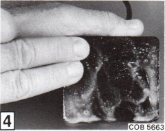
2. When the boat is launched after dry storage, the transducer will require several minutes to stabilize. If the transducer is accessible, the time can be reduced by rubbing the face of the transducer.

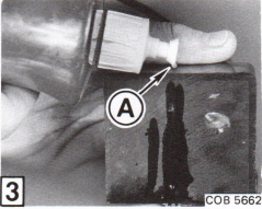
3. To remove gasoline and oil from the bottom face of the transducer use a mild soap solution @ to clean the face thoroughly. For ease of removing marine growth or calcium residue from the bottom face of the transducer, remove the growth or residue while wet. Marine growth and residue become hard and difficult to remove when dry. If a scraper is used to remove marine growth from the face of the transducer, use care not to gouge or scrape the bottom face of the transducer. Scrapes or gouges can cause air bubbles to flow across the transducer, causing erratic or false readings to the Tracker.

4. Coating the face of the transducer with anti-fouling paint is not recommended. If anti-fouling paint is mandatory, it should be applied with a thin, even coat of paint recommended for use on transducers. The boat should then be water tested to assure that the Tracker is functioning properly. If erratic or false readings are observed, the paint must be removed from the face of the transducer. Do not use any chemicals or solvents to remove paint. Use a scouring pad or a sanding block with 100 grit sandpaper to restore a flat, smooth surface.

5. If wiring connections are adequate and a poor or erratic signal is observed on the Tracker, remove the transducer and install another transducer. If improved signal is observed, original transducer is defective. If the transducer face is damaged, minor gouges or scrapes may be removed using a sanding block and 100 grit sandpaper.

Factory figure 2 for bulletin 2101Factory figure 3 for bulletin 2101Factory figure 4 for bulletin 2101
2 / 2

Tools, supplies and related parts

Suggested products related to this service bulletin. Verify fit and suitability before ordering.

Amazon: tools and supplies

Marine Outboard Service Tool Kit / Shop Towels

Search for these supplies on Amazon

Affiliate disclosure: EverythingOutboards may earn a commission from qualifying purchases. As an Amazon Associate, we earn from qualifying purchases.