2006–2010 Bulletin Index

2008-02(D): Installation and Predelivery

2009 Evinrude E-TEC 25–30 HP outboards. Factory bulletin pages 1–14 of 18. Additional pages will be added as completed.

Evinrude Johnson predelivery bulletin header
Date: December 14, 2008No. 2008-02(D)
MODELS: 2009 Evinrude® E-TEC® 25–30 HP
SUBJECT:Installation and Predelivery

Dear Evinrude/Johnson® Dealers:

This communication is to inform Evinrude E-TEC dealers of the requirements for installing 2009 Evinrude E-TEC 25–30 HP models.

Refer to the latest Predelivery and Installation Guide for:

  • Boat Rigging
  • Final Adjustments

Hull Preparation

Maximum Capacity

▲ WARNING

Do not overpower the boat by installing an outboard that exceeds the horsepower indicated on the boat's capacity plate. Overpowering could result in loss of control.

Before installing outboard:

  • Refer to the boat manufacturer's certification label for maximum horsepower rating.
  • Refer to ABYC Standards to determine the maximum horsepower capacity for boats without certification labeling.
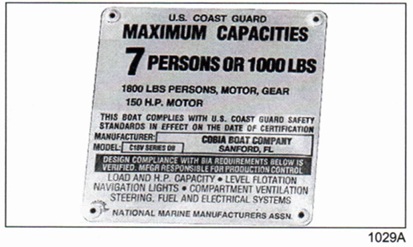
Factory maximum capacities plate, illustration 1029A, including original caption

Mounting Surface

Inspect transom surface prior to drilling mounting holes.

  • The transom should meet ABYC Standards.
  • The transom must be flat.
  • The transom angle should be approximately 14 degrees.
  • Check transom strength and height.

The stern brackets must contact the flat surface of the transom. Modify trim that prevents the stern brackets from resting against the transom surface. Do not modify stern brackets.

▲ WARNING

DO NOT install an outboard on a curved or irregular surface. Doing so can wear, bind, and damage components, causing loss of control.

Transom Clearances

Make sure the transom and splash well area provide adequate clearances:

  • The top edge of the transom should be wide enough to allow full steering travel. The ABYC standard for most single outboard installations is 33 in. (84 cm).
  • Check cable and hose routing clearances.
  • Make sure there is clearance for mounting bolts and washers. Check the inside area of the transom for obstructions before drilling holes.
Water Flow

Inspect the hull area directly in front of the mounting location.

  • Boat-mounted equipment should not create turbulence in the water flow directly in front of the outboard's gearcase. Turbulence or disruptions in the water flow directly in front of the gearcase will affect engine cooling and propeller performance.
  • Avoid locating outboard centerlines within 3 in. (76 mm) of bottom strakes or dual-outboard installations.

Mounting Hardware

WARNING

Use all mounting hardware supplied with the outboard to help ensure a secure installation. Substituting inferior hardware can result in loss of control.

The required outboard mounting bolts, backing plates, washers, and nuts are shipped with the outboard.

Refer to the outboard's parts catalog for alternate length mounting bolts or replacement parts.

  • Use only Evinrude/Johnson Genuine Parts or parts of equivalent type, strength, and material.
  • Use the mounting hardware provided with outboard whenever possible.

Transom Measuring and Drilling

Hull Centerline

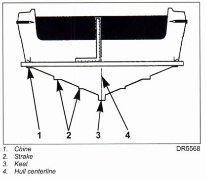
Use the chines of the boat as reference points to locate the centerline of the boat transom.

Use a straightedge to draw a line connecting port and starboard chines.

Use a framing square to accurately place a vertical line on the transom. The centerline of the hull should be in line with the keel, and perpendicular to the midpoint of the line connecting the chines.

Hull centerline, chine, strake, keel and hull centerline diagram

Transom Height

Make sure the transom height matches the length of the outboard to be installed.

  • A 19 to 21 in. (48.3 to 53.3 cm) transom height uses a 20 in. (50.8 cm) shaft outboard.
  • The shaft length of the outboard being installed should come close to matching the transom height of the boat.

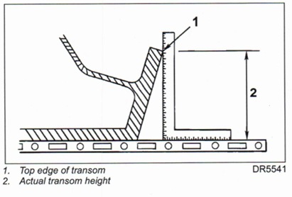
Determine transom height by measuring from the top edge of the transom, along the centerline.

Use a straightedge as a reference to extend the bottom of the boat.

Position the straightedge along centerline. The distance from the top edge of the straightedge to the top edge of the transom is the actual transom height.

Top edge of transom and actual transom height diagram

Transom Drilling Locations

Power Trim Models

All models use the standard ABYC 4-Bolt mounting pattern.

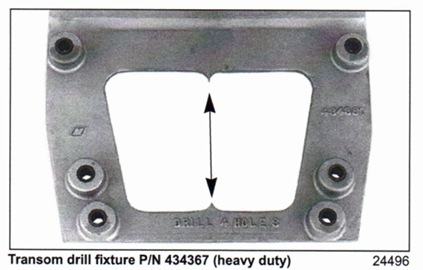
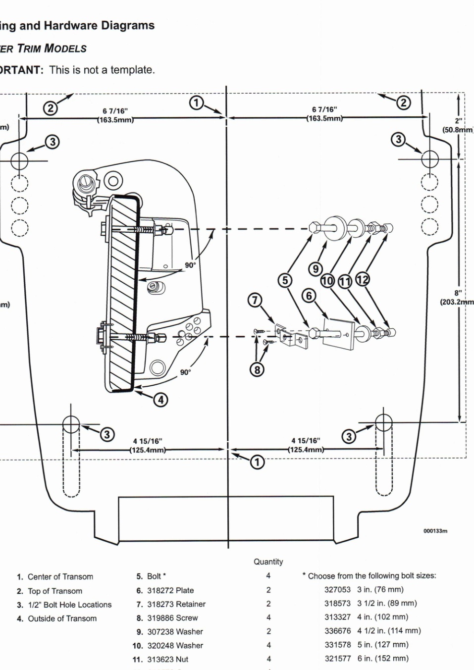
Transom drill fixture, P/N 434367 or P/N 385368, may be used as a guide for correct hole placement. If drill fixture is unavailable, refer to Drilling and Hardware Diagrams on p. 4 for measurements.

Position drill fixture on top of transom or bracket and align indicator points with centerline.

Transom drill fixture P/N 434367 (heavy duty), illustration 24496

The indicators are affected by the squareness of the top edge of the transom. If either side of the fixture must be raised more than ¼ in. (6 mm) above the transom's top surface to make both indicators align, the transom must be modified.

IMPORTANT: DO NOT assume that the top edge of the transom is straight. Position the drill fixture based on measurements aligning it to the bottom of the hull.

IMPORTANT: Maintain at least 1.75 in. (45 mm) of transom surface above the top mounting bolts.

Before drilling any mounting holes:

  • Make sure the hole locations provide enough clearance for mounting bolts and washers.
  • Check the inside area of the transom for obstructions.
  • Check transom height(s) at centerlines.

Drill four ½ in. (13 mm) mounting holes in the appropriate locations.

IMPORTANT: Be sure to drill the required holes perpendicular to transom surface.

Manual Tilt Models

Center the outboard on the transom (or mounting bracket) and tighten clamp screws by hand.

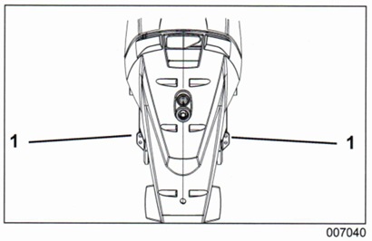
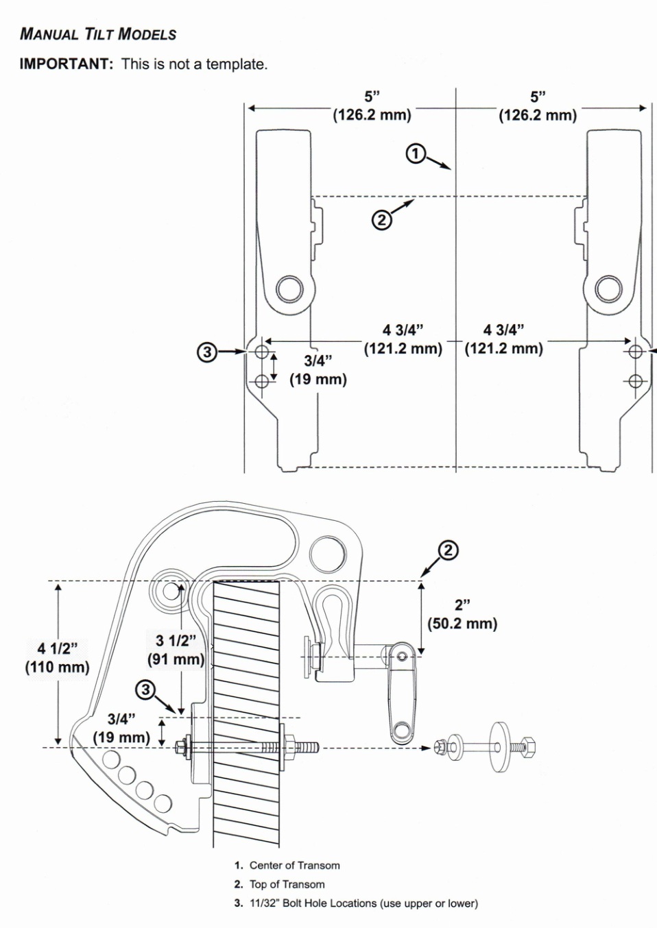
Use each stern bracket's mounting holes as a guide to drill holes through the transom.

  • 25-30 HP models require two 11/32 in. (8.7 mm) holes.
Manual tilt model stern bracket mounting-hole locations, illustration 007040
Original factory drilling and hardware diagrams, page 4
Original factory drilling and hardware diagrams, page 5

Lifting the Outboard

WARNING

To avoid personal injury, make sure the lifting capacity of the hoist is at least twice the weight of the outboard.

DO NOT allow the lift hook or chain from the hoist to come in contact with any part of the engine during lifting.

Open the shipping carton and remove packing material from top of carton.

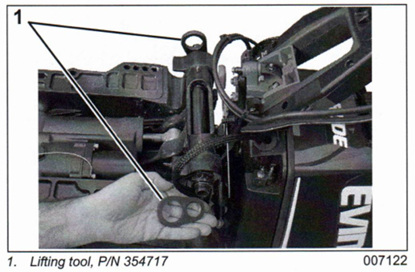
Install lifting tool, P/N 354717, on both sides of the tilt tube.

Lifting tool P/N 354717 fitted to tilt tube
WARNING

To avoid personal injury or outboard damage, be sure the lifting tool is fully threaded on both sides of the tilt tube.

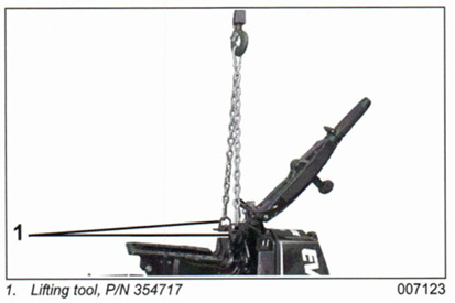
Use an appropriate chain, at least 36 inches (91 mm) long with two snap hooks each capable of lifting 500 lbs. (227 kg).

Attach hooks to lifting device and attach chain to hoist.

WARNING

Use this tool for horizontal lifting of 30 HP and smaller Evinrude E-TEC models ONLY.

DO NOT use this tool to lift outboards larger than 30 HP Evinrude E-TEC models.

To avoid personal injury and boat or outboard damage, DO NOT use this tool to install outboard onto boat transom. An outboard can unexpectedly tip.

Lift the engine out of the carton.

Lifting engine out of carton

Remove upper motor cover.

Place clean pad or cardboard on the floor.

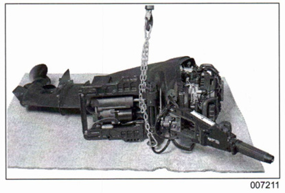
Lower outboard onto cardboard. Use hoist to carefully roll the outboard onto its port side.

WARNING

To avoid damage to the outboard, DO NOT allow the outboard to fall unrestrained.

Outboard lowered onto its port side

Remove chain from lifting tool.

Remove lifting tool from outboard.

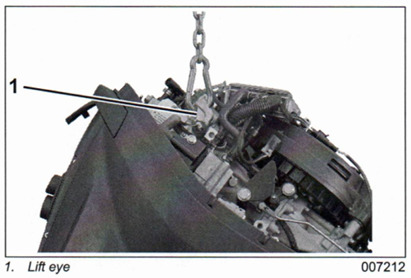
Attach chain to cast in lift eye on back of engine block.

WARNING

If the chain snap hooks are too large, the cast in lift eye could break causing the outboard to drop suddenly causing personal injury and damaging the outboard.

Lift eye, illustration 007212

Carefully lift engine with hoist.

WARNING

To avoid damage to the outboard, lift the outboard in one smooth motion. DO NOT allow the outboard to bounce.

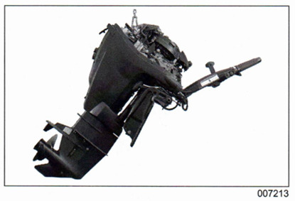
Outboard lifted by hoist, illustration 007213

Steering Systems

Mechanical Cables

All Evinrude outboards equipped with tilt tubes are designed to be compatible with mechanical steering systems that meet ABYC Standard P-17. Single-cable mechanical steering systems can be used on single or dual-outboard installations if an ABYC-approved steering link is used.

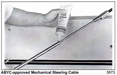
Extend the steering cable and lubricate the inner core before installation.

ABYC-approved mechanical steering cable, illustration 5873

IMPORTANT: Install steering cable through tilt tube before mounting outboard on transom. Tighten nut securely.

Steering Connector

Use steering connector kit, P/N 173699, to allow full steering travel.

Steering Connections

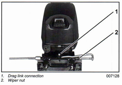
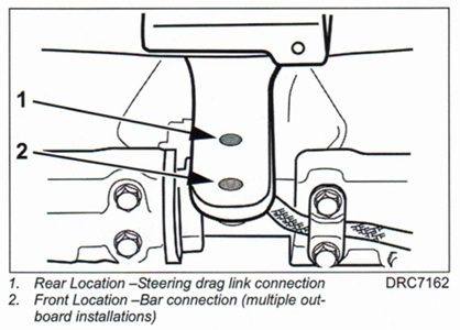
Install cable wiper nut on tilt tube and connect drag link to the rear location on the steering arm. For single engine, single cable applications the drag link should be installed in the rear hole.

Steering drag link connection and wiper nut, illustration 007128
Rear and front steering drag link locations, factory diagram

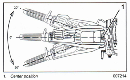
Tiller Handle Angle Setting

The tiller handle angle can be reset 20° to port or starboard.

1) Remove lock nut and screw from center position.

2) Set tiller arm to desired position. Loosely install screw.

Tiller handle angle settings, center position, illustration 007214

3) Check for proper steering clearance with outboard in fully tilted position and in normal operation position.

CAUTION

To avoid damaging the tiller handle when tilting the outboard up, position the outboard to clear obstacles in the motor well and boat.

4) Tighten screw to a torque of 18 to 20 ft.lbs. (25 to 27 N·m).

5) Hold screw with wrench and tighten lock nut to a torque of 18 to 20 ft.lbs. (25 to 27 N·m).

WARNING

Improper fastener installation when resetting the tiller handle could result in personal injury due to loss of boat control.

Outboard Mounting

IMPORTANT: Some rigging components, such as steering cables, must be fitted to the outboard before the outboard is mounted to the transom. Determine what equipment will be installed before mounting.

Mounting Height

Boat performance depends on outboard mounting height.

Generally, the anti-ventilation plate of the gearcase should align with the bottom of the hull. Conventional V-hulls often perform well with the anti-ventilation plate approximately 1 in. (25 mm) above the bottom of the hull.

Test outboard and boat performance at different heights until the best performance is achieved.

IMPORTANT: Be sure that outboard water pressure is not adversely affected by the mounting height of the outboard.

Mounting Bolt Installation

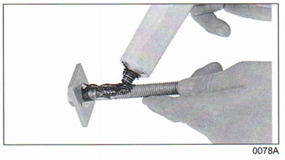
IMPORTANT: Use a marine sealant rated for above or below waterline use. RTV silicone is not approved for below waterline use. Polyurethane sealants are not easily removed and may damage outboard or boat mounting surfaces.

Apply marine sealer under the heads of bolts, on the mounting plates, and on the bolt shanks.

Applying marine sealer to mounting bolt, factory illustration

Power Trim Models

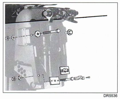
Assemble transom mounting plates on mounting bolts.

Install the mounting bolts through the transom from the inside of the boat.

Power trim transom mounting plate, factory illustration DR5536 with caption

Position the square aluminum transom mounting plates (when applicable) so the retainer holes are horizontal.

Position hex head of bolt with flats toward holes in the mounting plates. Install retainer over hex head of the bolt and secure it with screws provided.

Install all washers and nuts. Tighten to a torque of 40 ft. lbs. (54 N·m).

WARNING

If either side of the transom deforms or cracks when the bolts are tightened to their recommended torque, the transom construction may not be adequate or may be deteriorated. Structural failure of the transom could result in loss of boat control and injury to the occupants.

Manual Tilt Models

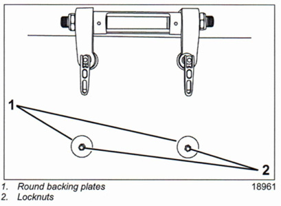
Install the mounting bolts through the stern bracket slots and the transom. Install round backing plates and locknuts onto bolts and tighten securely.

Manual tilt round backing plates and locknuts, factory illustration 1896 with caption

Outboard Rigging

Control Cable Installation

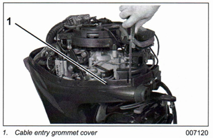
Remove cable entry grommet cover. Remove top half of cable entry grommet.

Cable entry grommet cover, factory illustration 007120 with caption

NOTE: Removal of lower motor covers is NOT required. Some of the images in this bulletin show lower covers removed for clear illustration.

Shift Cable

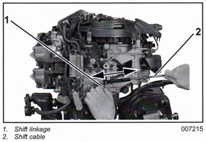
Confirm that the remote control, gearcase, shift linkage, and shift cable are in NEUTRAL.

Position shift cable on the shift lever pin. Install washer and retainer clip.

Hold the shift linkage in NEUTRAL and grab the shift cable firmly. Push and pull on the shift cable and observe the cable slack. Position the casing guide in the center of the slack.

Adjust the shift cable trunnion to align with the center of the trunnion block.

Shift linkage and shift cable, factory illustration 007215 with caption

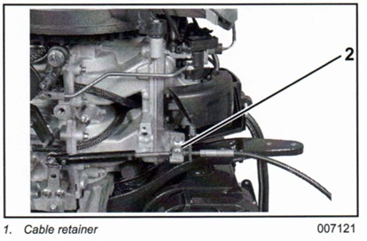
Install cable retainer and tighten screw to a torque of 60 to 84 in. lbs. (7 to 9.5 N·m).

Cable retainer, factory illustration 007121 with caption

Throttle Cable

Rotate the propeller shaft and shift the remote control into FORWARD. Next pull remote control lever half-way back to NEUTRAL.

Position throttle cable on the throttle lever pin. Install washer and retainer clip.

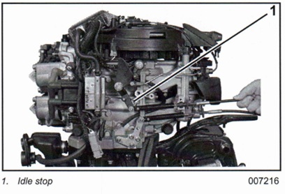
With remote control lever attached to the throttle linkage, pull cable to remove slack and ensure that the idle stop of the throttle linkage is against the crankcase.

Idle stop, factory illustration 007216 with caption

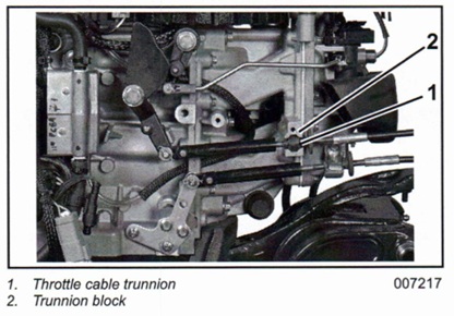
Adjust the throttle cable trunnion to align with the trunnion block. Place the throttle cable in the trunnion block.

IMPORTANT: Do not pre-load throttle cable. Make sure that the idle stop on the throttle linkage lightly contacts the crankcase when the remote control is in the IDLE position.

Throttle cable trunnion and trunnion block, factory illustration 007217 with caption

Install cable retainer and tighten screw to a torque of 60 to 84 in. lbs. (7 to 9.5 N·m).

Harness Routing

If removed, reinstall lower motor cover(s).

Place the bottom half of cable entry grommet into position in the lower motor cover.

Remove rubber membrane from grommet holes as needed.

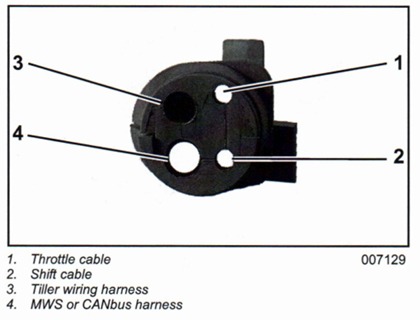
Install cables and wiring harness(es) through grommet as shown:

Factory cable entry grommet routing, illustration 007129 with caption

Route all wires to avoid contact with moving parts.

Electrical Harness Connections

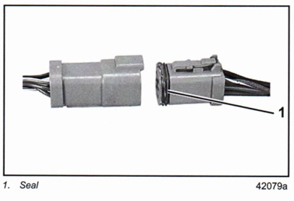
Before installing electrical connectors, check that the seal is in place. Clean off any dirt from connectors. Apply a light coat of Electrical Grease™ to the seal.

Factory connector seal, illustration 42079a with caption

Push MWS connectors together until securely latched.

The EMM provides tachometer and LOW OIL warning signals only. Refer to Engine Monitoring in the Operator’s Guide, for warning information.

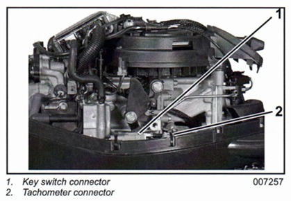
Route key switch and tachometer harness along the edge of the lower engine cover.

Factory key switch and tachometer connector locations, illustration 007257 with caption

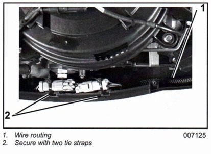
Secure connectors to lower motor cover with two tie straps as shown.

Factory wire routing and tie straps, illustration 007125 with caption

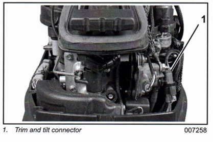
Route trim and tilt connector under air silencer. Use tie strap to secure connector as shown.

Factory trim and tilt connector, illustration 007258 with caption

Install top half of cable entry grommet.

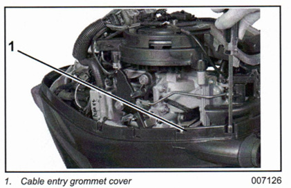
Install cable entry grommet cover.

Cable entry grommet cover, illustration 007126 with factory caption

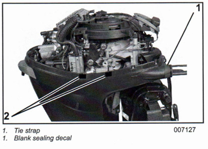
Tighten tie strap, P/N 320107, around the outside of the grommet to form a seal around the cables.
Position blank sealing decal, P/N 354709, on lip of lower motor cover at each tie strap to prevent water intrusion.

If sealing decal is not available, use an equivalent waterproof tape.

Tie strap and blank sealing decal, illustration 007127 with factory caption

Battery Cable

Install cable battery cables as shown.

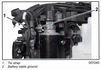
Use a tie strap to secure battery cables as shown.

Tie strap and battery cable ground, illustration 007240 with factory caption

Route battery cable through grommet of port lower motor cover.

BE SURE all harnesses and wires are not pinched, and do not interfere with moving throttle or shift linkages.
Fuel Requirements

WARNING

Gasoline is extremely flammable and highly explosive under certain conditions. Improper handling of fuel could result in property damage, serious injury or death.
Always turn off the outboard before fueling.

Never permit anyone other than an adult to refill the fuel tank.

Do not fill the fuel tank all the way to the top or fuel may overflow when it expands due to heating by the sun.

Remove portable fuel tanks from the boat before fueling.

Always wipe off any fuel spillage.

Do not smoke, allow open flames or sparks, or use electrical devices such as cellular phones in the vicinity of a fuel leak or while fueling.

Minimum Octane

Evinrude E-TEC outboards are certified to operate on unleaded automotive gasoline with an octane rating equal to or higher than:

  • 87 (R+M)/2 AKI, or
  • 90 RON

Use unleaded gasoline that contains methyl tertiary butyl ether (MTBE) ONLY if the MTBE content does not exceed 15% by volume.

Use alcohol-extended fuels ONLY if the alcohol content does not exceed:

  • 10% ethanol by volume
  • 5% methanol with 5% cosolvents by volume

When using alcohol-extended fuels, be aware of the following:

  • The boat’s fuel system may have different requirements regarding the use of alcohol fuels. Refer to the boat’s owner guide.
  • Alcohol attracts and holds moisture that can cause corrosion of metallic parts in the fuel system.
  • Alcohol blended fuel can cause engine performance problems.
  • All parts of the fuel system should be inspected frequently and replaced if signs of deterioration or fuel leakage are found. Inspect at least annually.

IMPORTANT: Always use fresh gasoline. Gasoline will oxidize, resulting in loss of octane and volatile compounds, as well as the production of gum and varnish deposits which can damage the outboard.

Additives

IMPORTANT: The only fuel additives approved for use in Evinrude outboards are 2+4® fuel conditioner and Evinrude/Johnson Fuel System Cleaner. Use of other fuel additives can result in poor performance or engine damage.

Evinrude/Johnson 2+4 Fuel Conditioner will help prevent gum and varnish deposits from forming in fuel system components and will remove moisture from the fuel system. It can be used continuously and should be used during any period when the outboard is not being operated on a regular basis. Its use will reduce spark plug fouling, fuel system icing, and fuel system component deterioration.

Evinrude/Johnson Fuel System Cleaner will help keep fuel injectors in good operating condition.

Fuel System Priming

Vent Line Clamp

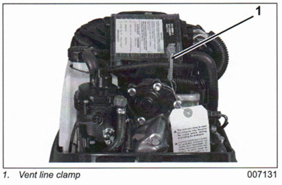
In compliance with Code of Federal Regulations, 49 CFR §173.220, all outboards using a fuel vapor separator must be shipped with a vent line clamp installed. This clamp must be removed before

priming the fuel system or starting the outboard for the first time.

Vent line clamp, factory illustration 007131 with original caption

IMPORTANT: Failure to remove the clamp may cause fuel starvation and poor running qualities.

Priming the Fuel System

▲ WARNING

Fuel vapors are highly flammable. Perform the following procedure in a well ventilated area. Extinguish all smoking materials and make certain no ignition sources are present.

The outboard must be primed when it is new or if run out of fuel.

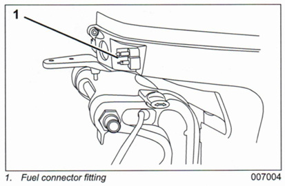
Connect the fuel hose to the fuel connector fitting.

Fuel connector fitting, factory illustration 007004 with original caption

Squeeze fuel primer bulb, outlet end up, until firm.

Observe all fuel lines, both in the boat and on the outboard. Repair any fuel leaks.

▲ WARNING

Failure to check for fuel leaks could allow a leak to go undetected, resulting in fire or explosion and may cause personal injury or property damage.

The high-pressure fuel circuits and injectors will prime as the outboard is cranked with the starter.

Oil Requirements

Evinrude/Johnson XD100, XD50 or XD30 are recommended for use in Evinrude E-TEC outboards. If these oils are not available you must use a TC-W3 certified oil.

Evinrude/Johnson XD100 outboard oil is highly recommended for all conditions and applications.

When operating in conditions under 40°F (4°C), Evinrude/Johnson XD100 oil is recommended. When operating in conditions under 32°F (0°C), Evinrude/Johnson XD100 oil, must be used.

IMPORTANT: Failure to follow oil specifications could void the engine warranty if a lubrication-related failure occurs.

Oil Injection Rate

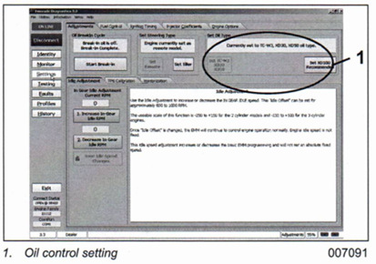
The Engine Management Module (EMM) controls the oil injection rate based on engine RPM. Evinrude Diagnostics software provides an option to change the oil type setting on these models.

The TC-W3 oil type setting is the standard setting for all outboards. Set TC-W3 for:

  • Operation with all TC-W3 outboard oils including XD30, XD50, or XD100.
  • Applications requiring maximum lubrication.
  • Extreme applications (commercial use, racing or other high performance applications).

Use the TC-W3 oil type setting with XD-100 outboard oil in extreme applications.

The XD100 setting provides an option to run the outboard at a reduced oil injection rate. This setting REQUIRES the use of Evinrude XD100 outboard lubricant.

Use the XD100 setting for:

  • Conventional use (runabouts, cruisers)
  • Moderate applications
Oil control setting, factory illustration 007091 with caption

Running an Evinrude E-TEC outboard on other grades of oil while set to the XD100 oil type setting will result in increased engine wear and shortened outboard life.

Powerhead oil programming labels are provided to identify EMM oil programming. Install the correct label to alert user to specific oil requirements.

Filling the Oil Tank

IMPORTANT: The oil tank capacity is 1.5 quarts (1.4 liters).

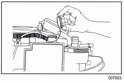
Remove the upper motor cover. Remove the filler cap and fill the tank with the recommended outboard lubricant.

Filling the oil tank, factory illustration 007003 with caption

Replace the filler cap and tighten securely. Reinstall the engine cover.

Priming the Oil System

The oiling system must be primed before using the outboard if:

  • The outboard is new.
  • The outboard is run completely out of oil.
  • The outboard is transported or stored in a horizontal position (laid down).

Follow these steps for initial outboard set-up:

  • Fill the oil tank with XD100, XD50, or XD30 oil.
  • Use Evinrude Diagnostics software to confirm that the EMM is programmed for the type of oil being used.
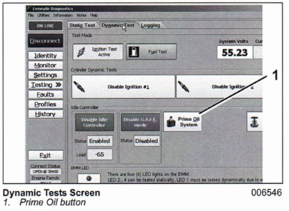
  • Start the outboard and use Evinrude Diagnostics software oil priming function for a minimum of 90 seconds to make sure the system is completely primed.
Dynamic Tests Screen, Prime Oil button, illustration 006546 with caption

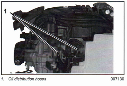
Observe oil flow through the oil distribution hoses.

Oil distribution hoses, factory illustration 007130 with caption

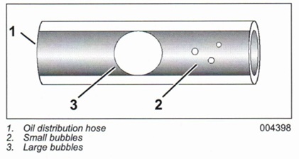
Small bubbles are acceptable. Large bubbles must be eliminated through continued priming.

Oil distribution hose, small and large bubbles, illustration 004398

IMPORTANT: All clear “blue” oil distribution hoses on the powerhead should fill with oil as the air is purged from the lines.

Repair any oil leaks.

The oiling system can also be primed using the Self-Winterizing feature if the diagnostic software is not available. Refer to Long Term Storage in the Operator’s Guide.

Break-In Oil

At delivery, advise the customer that new outboards are programmed to use additional oil during the first two hours of operation above 2000 RPM.

IMPORTANT: The operator must monitor the oil tank level to confirm oil consumption. This may require several hours of operation above idle.

Running Checks

WARNING

DO NOT run outboard without a water supply to the outboard’s cooling system. Cooling system and/or powerhead damage could occur.

DANGER

DO NOT run the engine indoors or without adequate ventilation or permit exhaust fumes to accumulate in confined areas. Engine exhaust contains carbon monoxide which, if inhaled, can cause serious brain damage or death.

DANGER

Contact with a rotating propeller is likely to result in serious injury or death. Assure the engine and prop area is clear of people and objects before starting engine or operating boat. Do not allow anyone near a propeller, even when the engine is off. Blades can be sharp and the propeller can continue to turn even after the engine is off.

Fuel System

Perform running checks of the fuel system by following these steps:

  • Squeeze fuel primer bulb until hard or activate electric primer. Observe all fuel hoses and connections. Repair any leaks.
  • Start outboard. Inspect all hoses and connections. Repair any leaks or mis-routed hoses immediately.

Emergency Stop / Key Switch

Check emergency stop function. With outboard running at IDLE, pull safety lanyard from emergency stop switch. Outboard must stop immediately.

Remote Control Operation

Make sure that control can be easily moved into all gear and throttle settings. Do not shift remote control when outboard is not running.

Start-In-Gear Prevention

WARNING

Make certain that the outboard will not start when in gear. The start-in-gear prevention feature is required by the United States Coast Guard to help prevent personal injuries.

Start outboard and shift to FORWARD.

Turn outboard OFF while control is in FORWARD.

Try to restart the outboard. Outboard should not start.

Shift back to NEUTRAL and restart outboard.

Shift to REVERSE. Turn outboard OFF while control is in REVERSE.

Try to restart the outboard. Outboard should not start.

Tachometer Pulse Setting

Confirm accuracy of tachometer reading.

  • Adjust dial on back of tachometer to required setting (the outboard should not be running).
Outboard ModelTachometer Setting
25-30 HP6 Pulse or 12 Pole

Water Pump Overboard Indicator

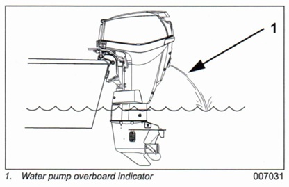
A steady stream of water should flow from the overboard indicator.

Water pump overboard indicator, factory illustration 007031 with caption

Operating Temperature

An outboard run at idle speed should achieve a temperature based on the engine’s thermostatic control. In general, the powerhead temperature should reach at least 104°F (40°C) after five minutes of idling. Check that the powerhead reaches idle temperature.

Idle Speed

Make sure the outboard idles within the specified idle RPM range. If the outboard is run on a flushing device, the idle speed and quality may not be representative of actual in water use.

Break-In

When the outboard is delivered, refer the customer to the break-in information in the Operator’s Guide.

The Engine Management Module (EMM) automatically supplies extra oil to the engine during the first two hours of operation, above 2000 RPM.

Use Evinrude Diagnostics software to confirm that the break-in program has been started.

Propellers

Propeller Selection

WARNING

Selection of the wrong propeller could reduce engine service life, affect boat performance, or cause serious damage to the powerhead.

Water testing with various propeller designs and sizes is the best method of propeller selection.

The correct propeller, under normal load conditions, will allow the engine to run near the midpoint of the RPM operating range at full throttle.

IMPORTANT: If the propeller blades have too much pitch, the engine will operate below its normal range at full throttle. Power will be lost, and powerhead damage could occur. If the propeller blades have too little pitch, the engine will operate above its normal range and damage from overspeeding could occur.

When selecting a propeller, consider the following:

  • Use an accurate tachometer to determine the engine’s full-throttle RPM.
  • The outboard should be trimmed for top speed.
  • Select a propeller that suits the customer’s application and allows the engine to run near the midpoint of the full-throttle operating range when the boat has a normal load.
  • Occasionally, one propeller will not cover a wide range of boat applications. In such cases, it might be necessary to have a propeller for each situation.
  • Refer to the Evinrude/Johnson Genuine Parts and Accessories Catalog for propeller styles and sizes.

Propeller Hardware Installation

WARNING

When servicing the propeller, always shift the outboard to NEUTRAL, turn the key switch OFF, and twist and remove all spark plug leads so the engine cannot be started accidentally.

Apply Triple-Guard grease to the entire propeller shaft before installing the propeller.

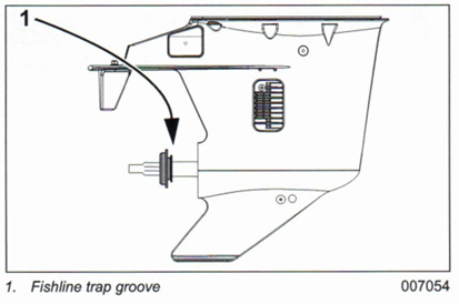
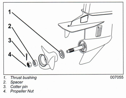
Install thrust bushing onto propeller shaft with fishing line trap groove facing forward. Taper of bushing must match taper of propeller shaft.

Factory illustration 007054, fishing line trap groove, including original caption

Install propeller on propeller shaft by aligning splines and pushing until seated on the thrust bushing.

Install the spacer, engaging the propeller shaft splines.

Factory illustration 007055, thrust bushing, spacer, cotter pin and propeller nut, with original captions

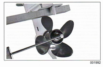
Wedge a block of wood between propeller blade and the anti-ventilation plate.

Factory photograph 001992, block of wood holding propeller while tightening

Install the propeller nut and tighten to a torque of:

  • 120 to 144 in. lbs. (13.6 to 16.3 N·m)

If cotter pin holes in the propeller nut and propeller shaft are not aligned, tighten the nut until they are in line. Do not loosen.

Insert a new cotter pin through the propeller nut and shaft. Bend its ends over the nut to secure the assembly.

After fastening propeller nut, make sure outboard is in NEUTRAL and carefully spin propeller. Propeller must turn freely and should not spin off center. If propeller appears to wobble, check for possible bent propeller shaft.

Special tools referenced in this bulletin

Transom Drill Fixture, P/N 434367 - mounting-hole layout and drilling.

Lifting Tool, P/N 354717 - lifting and handling the outboard.

Return to the 2006–2010 bulletin index