2006–2010 Bulletin Index

BRP Service Bulletin 2010-03(S): Gearcase Alignment Gauge Kit

Issued March 26, 2010, this bulletin revises procedures for gearcase alignment checks on Evinrude E-TEC 75–300 HP outboards and identifies additional components for kit P/N 5006349. It replaces Service Bulletin 2004-09(S).

Evinrude Johnson Service Bulletin header
Date: March 26, 2010No. 2010-03(S)
MODELS: Evinrude E-TEC 75–300 HP outboards
SUBJECT:Gearcase Alignment Gauge Kit, P/N 5006349
Replaces Service Bulletin 2004-09(S)

Dear Evinrude/Johnson Dealers:

This communication is to inform Evinrude and Johnson dealers that additional components are available for use with the Gearcase Alignment Gauge Kit, P/N 5006349. The instructions for using the kit have also been revised.

The gearcase alignment gauge kit includes the following components.
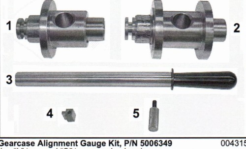
Gearcase Alignment Gauge Kit, P/N 5006349: 1. “L” type and “O” type gauging head; 2. “M” type gauging head; 3. Gauging shaft; 4. Retainer; 5. Thumb screw.

For individual replacement components for this kit, contact Meyer Engineering, 1139 Lewis Avenue, Winthrop Harbor, IL 60096–1428, 847–746–1500.

Use the gearcase alignment gauge kit to check the condition of all late model V4 and V6 gearcase housings before reassembly.

Additional components have been developed since the gearcase alignment gauge kit was introduced. The following tools are available individually to support the Gearcase Alignment Gauge Kit, P/N 5006349, and should be ordered from

Evinrude/Johnson Genuine Parts and Accessories.
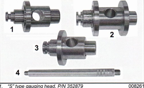
1. “S” type gauging head, P/N 352879; 2. “M2” type gauging head, P/N 5007749; 3. “L2” type gauging head, P/N 5007750; 4. Gauge remover shaft, P/N 354718.

INSTRUCTIONS

Check the alignment of the gearcase housing on gearcase assemblies that have experienced impact damage and/or internal bearing and gear failure.

NOTICE: Distorted gearcase housings affect driveshaft to propeller shaft alignment and gear alignment. Failure to properly identify distorted gearcase housings can result in replacement gear failure. This type of failure is NOT covered by warranty.

The gearcase alignment gauge kit components assemble to the forward bearing housing of a standard rotation gearcase and Driver Handle, P/N 311880 (existing tool), or Gauge Remover Shaft, P/N 354718.

Assemble as indicated to check all V4 (“S” and “S2” types) and V6 gearcase housings (1979 and newer with 4 hole water inlets, “O,” “L,” “L2,” “M,” and “M2” types).
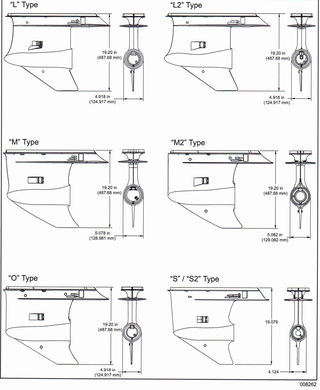
Refer to “GEARCASE IDENTIFICATION” on page 5 to properly identify gearcase type.

IMPORTANT: Disassemble and thoroughly clean gearcase housing and reinstall pinion bearing before installing the assembled gearcase alignment gauge into gearcase housing.

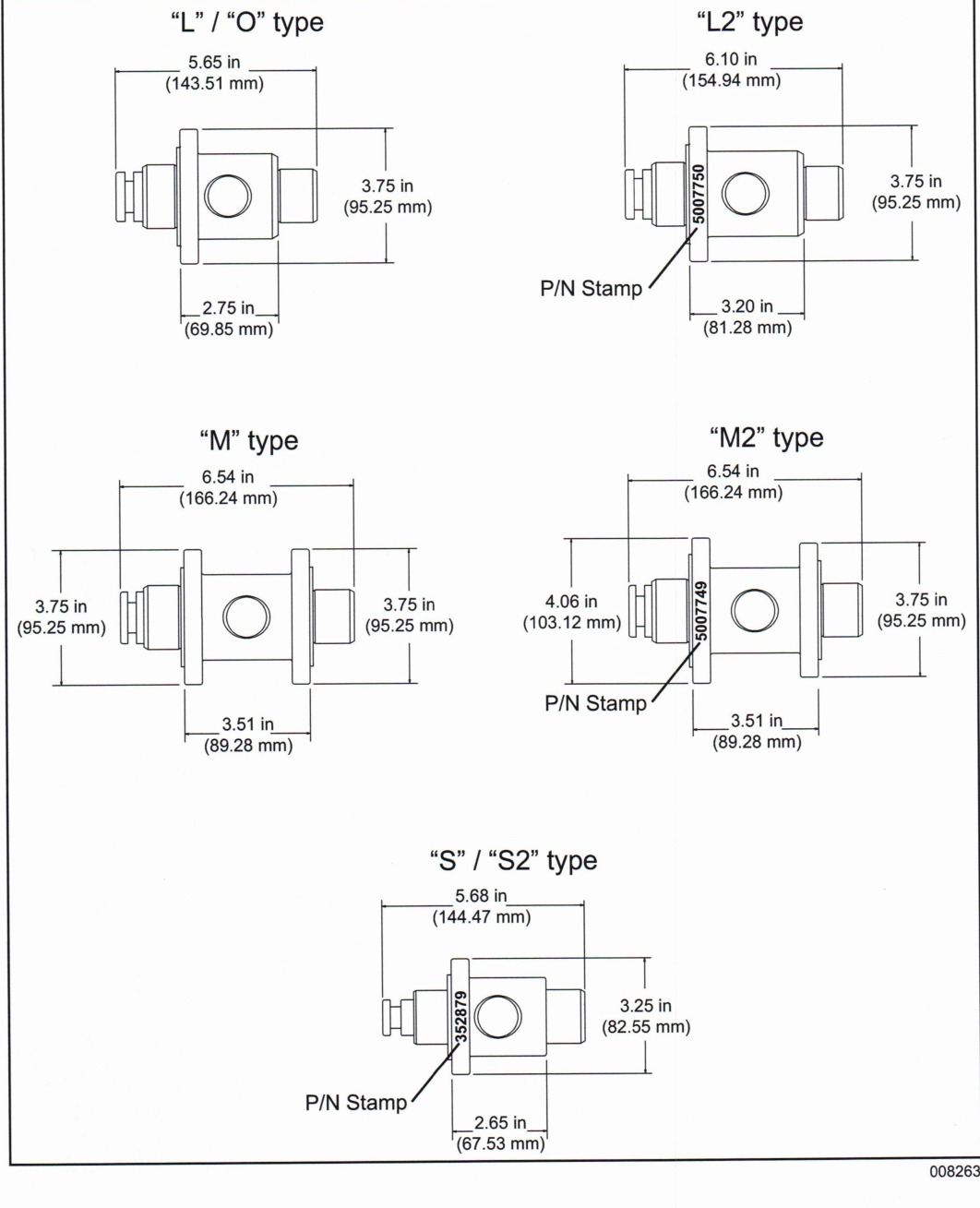
Select the correct gauging head. Refer to “GAUGING HEAD IDENTIFICATION” on page 6. Assemble gauging head with forward thrust bearing and washer onto forward bearing housing. Install the retainer in place of shift lever. Install shift pin.

“S,” “S2,” “O,” “L” and “M” Type Gearcases

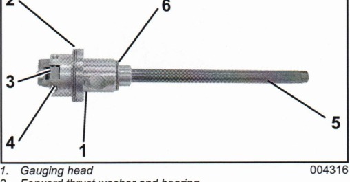
Thread Driver Handle, P/N 311880, into back of gauging head and tighten. Gauge Remover Shaft, P/N 354718, can be used if driver handle is not available. Position reverse thrust bearing and washer on gauging head.

1. Gauging head; 2. Forward thrust washer and bearing; 3. Retainer; 4. Shift pin; 5. Driver handle, P/N 311880; 6. Reverse thrust bearing and washer.

“L2” and “M2” Type Gearcases

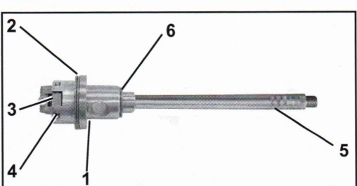
Thread Gauge Remover Shaft, P/N 354718 into back of gauging head and tighten. Position reverse thrust bearing and washer on gauging head.

1. Gauging head; 2. Forward thrust washer and bearing; 3. Retainer; 4. Shift pin; 5. Gauge remover shaft, P/N 354718; 6. Reverse thrust bearing and washer.

NOTICE: The gauge remover shaft MUST be used to remove gauging head, forward thrust bearing and forward bearing housing from “L2” and “M2” type gearcase housings.

All Gearcases

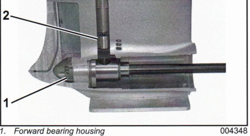
Insert assembly into cleaned gearcase housing. Make sure that forward bearing housing seats completely into front of gearcase housing.

1. Forward bearing housing; 2. Pinion bearing, assembled.

“S,” “S2,” “O,” “L” and “M” Type Gearcases

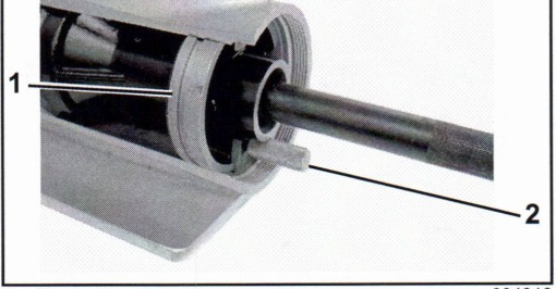
Temporarily install the propeller shaft bearing housing without large O-rings (or locking wedge, if equipped). Bearing housing must be fully seated in gearcase housing. Install lower tab retainer in housing and secure with thumb screw (if equipped).

1. Bearing housing; 2. Thumb screw.

“L2” and “M2” Type Gearcases

Grease the machined side surfaces of propeller shaft bearing housing. Do NOT install the propeller shaft bearing housing large O-rings.

Align propeller shaft bearing housing into gearcase.

“L2” Gearcase: Align screw holes with retainer slots in gearcase.

“M2” Gearcase: Align retaining holes in propeller shaft bearing housing with screw holes in

gearcase. Thread Alignment Pins, P/N 354140, into gearcase.

Seat the propeller shaft bearing housing with:

  • Gearcase Fixture, P/N 354059
  • Installer Handle, P/N 345822
  • Propeller Shaft Bearing Housing Installer, P/N 354058, “L2” type, or P/N 354057, “M2” type

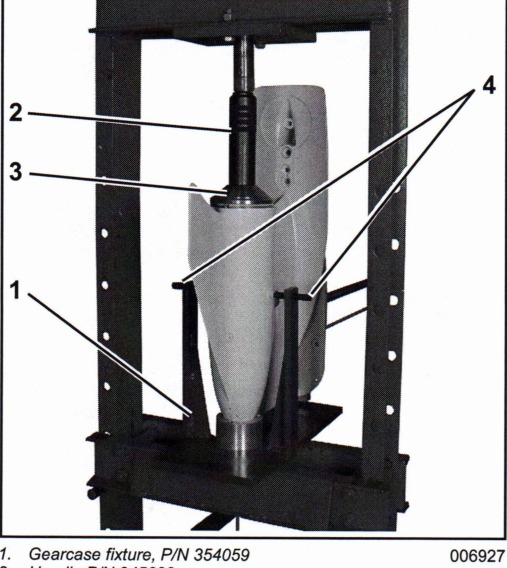
Align and level gearcase assembly in fixture as shown. Secure fixture to floor press. Use an appropriate floor press (10 ton or greater) to seat housing into gearcase.

1. Gearcase fixture, P/N 354059; 2. Handle P/N 345822; 3. Propeller shaft bearing housing installer; 4. Vertical alignment screws.

The propeller shaft bearing housing must be completely seated in gearcase.

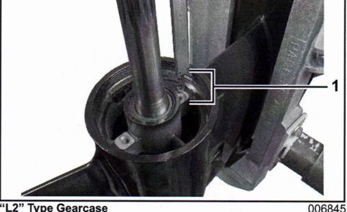
Check the depth from gearcase housing to retainer tab surface on propeller shaft bearing housing. Depth for an “L2” gearcase is approximately 1 in. (25.4 mm).

“L2” Type Gearcase: 1. 1 in. (25.4 mm).

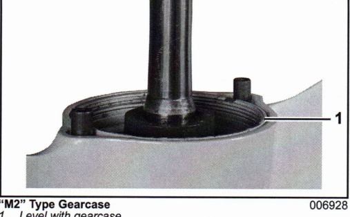
Check the depth from gearcase housing to propeller shaft bearing housing. Depth for an “M2” gearcase is approximately level with gearcase.

“M2” Type Gearcase: 1. Level with gearcase.

All Gearcases

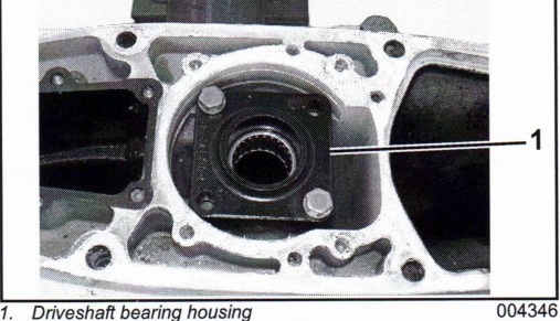
Temporarily install driveshaft bearing housing without seals and O-ring into gearcase housing and secure with two (2) screws. Bearing housing must be fully seated in gearcase housing.

1. Driveshaft bearing housing.

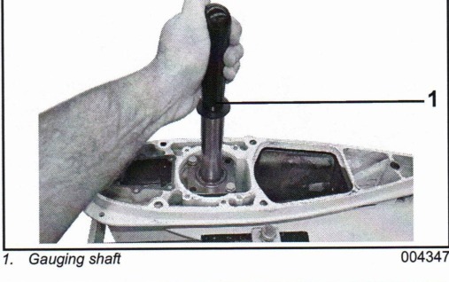
Use driver handle to turn gauging head as needed. Position gauging head to allow gauging shaft to slide easily into alignment hole in gauging head.

IMPORTANT: DO NOT force shaft into alignment hole. Shaft MUST slide easily into hole of gauging head. If shaft does not slide into hole, gearcase housing is damaged and must be replaced.

1. Gauging shaft.
1. Gauging shaft.
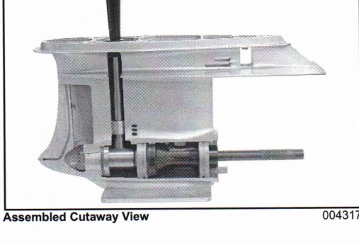
Assembled Cutaway View.

Remove gauging shaft from gearcase assembly BEFORE removing the propeller shaft bearing housing from the gearcase.

“L2” and “M2” Type Gearcases

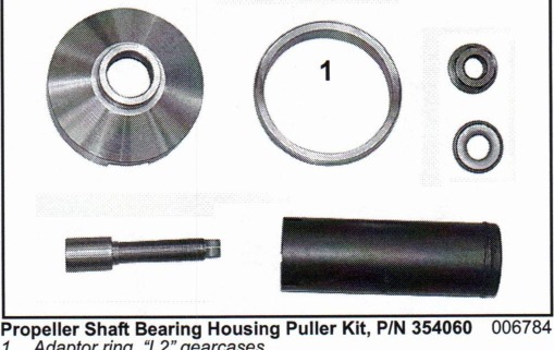
Remove the propeller shaft bearing housing from the gearcase using Propeller Shaft Bearing Housing Puller Kit, P/N 354060.

IMPORTANT: Use the adaptor ring included with the propeller shaft bearing housing puller kit to remove the propeller shaft bearing housing from “L2” type gearcases.

Propeller Shaft Bearing Housing Puller Kit, P/N 354060. 1. Adaptor ring, “L2” gearcases.

DO NOT use tools designed to push on the propeller shaft. Pushing force against the propeller shaft could damage the forward gear thrust bearing or thrust washer.

GEARCASE IDENTIFICATION

Original factory gearcase identification diagrams and dimensions

GAUGING HEAD IDENTIFICATION

Original factory gauging head identification diagrams and dimensions

Return to the 2006–2010 bulletin index

Related tools and supplies

Click here to search on Amazon

Click here to search on eBay

As an Amazon Associate, EverythingOutboards earns from qualifying purchases. Affiliate links may earn a commission.