Johnson SB-1015 - 9½ HP Service Information
Issued April 9, 1964, this six-page Johnson service bulletin describes inspection and tuning procedures for the 1964 MQ(L)-10S 9½ HP outboard. It addresses engine break-in, vibration, crankcase drain valves, breaker point timing, carburetor synchronization, float level and idle adjustment.

April 9, 1964
SUBJECT: SERVICE INFORMATION
ON MODELS: 9½ H.P., MQ(L)-10S
A number of check areas are outlined in this bulletin which the dealer should find helpful when attempting to correct conditions of less than desirable idle performance on 1964 - 9½ HP engines. It must be remembered, however, that the accepted time element for outboard engine break-in is normally considered to be from between 15 to 25 hours - the exact amount of time varying, of course, from engine to engine; and that in reality little precise tuning can be achieved until the engine has been broken-in thoroughly (rings seated, etc.).
We would like to mention also, that in view of the closely regulated break-in specifications that apply to all 1964 engines, the amount of time required for complete engine break-in could increase slightly over past model years. Here again the exact time element may vary from engine to engine, but generally speaking the average increase encountered will be somewhere between two to five hours.
The areas that may require attention will be listed under the following group of headings. Review this information now so that you will be well versed on the procedure when the busy season begins.
B - Inspect and/or clean crankcase drain valves.
C - Ignition breaker point timing.
D - Checking synchronization - carburetor and ignition.
E - Synchronization adjustment - carburetor and ignition.
F - Checking and/or adjusting float level.
G - Adjusting engine idle.
Proceed as follows:
A - ADJUSTING VIBRATION DAMPER.
The 9½ HP vibration damper has been designed to keep engine vibration at an absolute minimum during slow speed operation. This is one of the features that makes this engine ideally suited for the fisherman, since smooth engine operation at trolling speed is important to him.
After many hours of engine operation the vibration dampening pad may wear slightly - the affect being a slight increase in engine vibration at slow speeds. The damper may, however, be easily re-adjusted as follows.
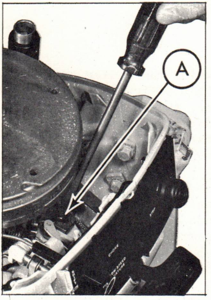
- Loosen vibration damper adjusting screw (Arrow A, Fig. 1) one complete turn. Then re-tighten screw securely. Specified tension for this screw is 4-5 foot pounds.
NOTE: During adjustment, the two springs which are hooked to the damper act to draw it firmly against the dampener pad as soon as the adjusting screw is loosened. Thus wear is compensated for by merely loosening and re-tightening the adjusting screw.
B. INSPECT AND/OR CLEAN CRANKCASE DRAIN VALVES.
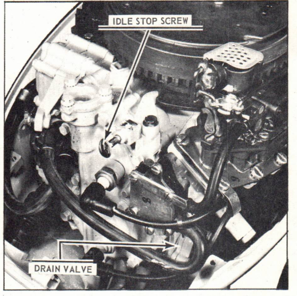
With a little care, the crankcase drain valve assembly (Fig. 2) can be removed for inspection and cleaning. This operation is important and is recommended for any engine that has a minimum of ten hours running time. A 5/16 open end or box end wrench is required for removal of the two drain valve screws. Removal of fuel pump makes crankcase drain assembly more accessible.
Upon removing drain valve assembly from engine, remove valves from plate and wash plate in cleaning solvent. Blow dry with air hose and hold plate up to sunlight, sighting through two small drain orifices. These orifices must be clear (unobstructed). After drain plate has been cleaned thoroughly, assemble valves and back strips making sure that valves are seating properly and that back strips have not been installed backwards.
Use new gaskets and re-assemble drain valve assembly to motor.
C. IGNITION BREAKER POINT TIMING.
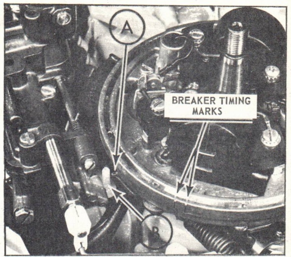
Breaker point timing is checked in normal fashion on the 9½ HP engine by using a continuity meter and timing fixture. The same timing fixture from set #376969 that is used on the 1963 - 10 HP engine will fit the 9½ HP crankshaft. Armature plate timing marks used in this operation are indicated on Fig. 3.
For optimum performance, points must be in good condition (not severely pitted) and each set must be adjusted so that it breaks contact as the respective timing fixture mark appears exactly halfway between the two breaker timing marks on the armature plate. Accurate breaker point adjustment is very important.
D. CHECKING SYNCHRONIZATION - CARBURETOR AND IGNITION.
- Retard throttle to idle by turning twist grip to "Stop" position.
- Advance twist grip slowly while watching carburetor throttle shaft. Stop the exact moment throttle valve starts to open.
- Magneto cam timing mark (Arrow A, Fig. 3) should be in exact alignment with center of nylon cam follower (Arrow B, Fig. 3). If timing mark is not aligned with center of follower, proceed with synchronization adjustment.
E. SYNCHRONIZATION ADJUSTMENT - CARBURETOR AND IGNITION.
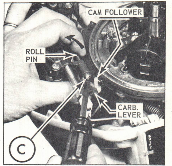
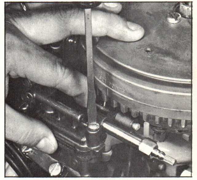
NOTE: Flywheel is shown removed in Fig. 4 to illustrate location of timing mark only. It is not normally necessary to remove flywheel during carburetor/ignition synchronizing operation.
- By turning twist grip, move cam timing mark into exact alignment with center of nylon cam follower.
- Loosen carburetor lever adjusting screw (Arrow C, Fig. 4).
- Twist carburetor shaft roll pin counter-clockwise with index finger, closing throttle valve, and at same time push carburetor lever against nylon cam follower - as shown in Fig. 4. While holding throttle valve closed and lever against cam follower, tighten lever adjusting screw securely.
- Check adjustment by retarding throttle to "Stop" position, followed by advancing throttle slowly (using twist grip) while watching carburetor throttle shaft. Stop advancing twist grip the exact moment throttle valve starts to open. At this point, timing mark should be in exact alignment with center of nylon cam follower. If not - repeat Steps E1, E2, E3 and E4 until this adjustment is accurate.
- Once above adjustment has been made, the magneto cam contour will automatically provide a wide open throttle when the twist grip is moved to maximum fast position.
F. CHECKING AND/OR ADJUSTING FLOAT LEVEL.
- Remove choke actuating rod, slow speed needle knob and gas hose from carburetor body.
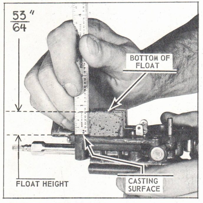
- Remove and invert carburetor body to check float level. Correct float height is 53/64" when measured as shown in Fig. 5, (with carburetor body gasket removed).
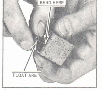
- If float is not set to the specified height, remove float from carburetor body and carefully bend float arm as shown in Fig. 6 to achieve correct setting. Repeat and check this adjustment until float height is correct.
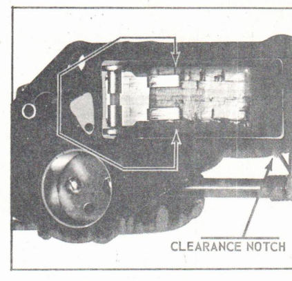
- After re-installing float in carburetor body, check clearance between sides of float and float cover cavity to make sure float is centered in the cavity (Arrows, Fig. 7). If float is not centered evenly, slight side clearance adjustment will be necessary to prevent float from dragging against float chamber wall. Re-check float height after adjusting side clearance of float.
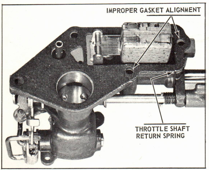
- Install a new float chamber gasket (309741) and check alignment of holes in gasket with corresponding holes in carburetor body. In event these holes are kept from aligning properly by the return spring (Fig. 8), a small notch may be cut in gasket for throttle shaft return spring clearance. See notched gasket in Fig. 7, showing correct gasket alignment.
- Assemble carb. body to float chamber. Hold body in alignment with float chamber as shown in Fig. 9 while tightening carburetor body screws to assure correct centering of float in float chamber. (NOTE: Throttle shaft return spring tends to push body out of alignment with float chamber if not properly held in position during tightening. Future production carburetors will include a spring boss which will eliminate interference as explained in this step and in step five).
G. ADJUSTING ENGINE IDLE
Engine idle adjustment is very important on all outboard engines, but perhaps it is even more important on fishing models than others, since fishing motors are operated at trolling speeds for extended periods of time. Therefore, this adjustment should follow all other items listed in this bulletin so that the dealer can assure himself of having everything else in order before attempting to make the slow speed jet and engine idle speed adjustments.
- Seat slow speed needle gently and back out 5/8 turn - initial setting.
- Run engine in test tank allowing it to reach normal operating temperature.
- Adjust idle stop screw in (Fig. 2) so that engine speed is approximately 800 RPM (using tachometer). Adjust slow speed needle midpoint between leanest and richest settings at which engine will run.
- Re-adjust idle stop screw to bring final engine idle speed to between 500-550 R.P.M.
- Install slow speed needle knob.
NOTE: Dealers may notice the evidence of a lean spot at part throttle on some new 9½ HP engines which may be difficult to eliminate by slow speed jet adjustment. This is simply a condition that exists on some new engines until the piston rings become seated; therefore, too much time should not be spent in attempting to adjust this condition out of the engine until it has been thoroughly broken-in. Usually fifteen hours is ample time for break-in on a 9½ HP engine.
Robert Compton
Administrative Assistant
RC:eb
NOTE: Post on MQ-9½ HP index under heading "MISCELLANEOUS".
Historical references and specifications
Models: MQ(L)-10S, 1964 Johnson 9½ HP. Factory timing fixture set: 376969. Float chamber gasket: 309741. Float height: 53/64 inch. Final idle: 500-550 RPM. Damper screw: 4-5 foot pounds.
These specifications are transcribed from the historical factory bulletin and should be checked against the original document before servicing an engine.