Johnson Service Bulletin SB-1040 - Checking the Transistor Charging Circuit
Issued February 3, 1965, this bulletin explains charging circuit and transistor voltage regulator checks for 1965 Johnson 75 and 90 HP V4A and V4M engines, including the factory jumper-wire method and charging-voltage limits.
February 3, 1965SB-#1040
SUBJECT: CHECKING THE TRANSISTOR CHARGING CIRCUIT
ON ENGINES: 1965 75 & 90 HP MODELS V4A and V4M
Checking charging circuit:
1. Disconnect plug in connector at voltage regulator.
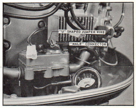
Figure 1
A. Cut and bend a short 1 1/2" wire into a "U" shape, which is used as a jumper wire.
B. Insert "U" shaped wire into "male" nylon connector, as shown in figure 1.
2. The voltage to the "on green" light on the dash cannot be controlled, as we eliminate the transistor voltage regulator in making the test. As a precautionary measure, remove the "on green" light bulb, as the uncontrollable voltage could burn it out.
3. Start and run engine at 2000 to 2200 RPM - watch the ammeter in making this check.
A. If ammeter shows a full charge, the charging system is okay - see figure 1.
B. If ammeter shows a half charge (10 amp.), one set of diodes are not working. Shut off engine, disconnect battery, and test both the positive and negative set of diodes. Replace defective set of diodes, connect battery, restart, and recheck ammeter which should read 20 amps.
PAGE 2SERVICE BULLETIN SB-#1040
JOHNSON MOTORS, DIVISION OF OUTBOARD MARINE CORPORATION, WAUKEGAN, ILLINOIS 60086
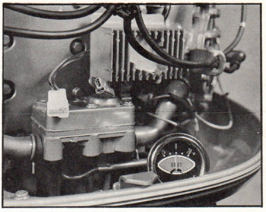
C. If ammeter shows no charge (see figure 2):
a. The 60 amp. fuse might be burned out. b. Both sets of diodes are not working. c. Stator windings or wires are shorted or open. d. The ammeter might be defective.
Checking voltage output:
As there is no bench test for the solid state regulator, it must be checked on the engine while operating. The battery should be fully charged in making this test. Note: connect regulator back into circuit.
1. Run engine for 20 minutes to assure battery charge and to warm up the transistor voltage regulator.
Figure 2
2. Shut engine off and connect a volt meter "+" lead to red wire at regulator two-way connector and "-" lead to engine for ground. Restart engine and run at 2000 to 2200 RPM. When the ammeter shows 5-10 amps, the voltage reading must not exceed 15.0 volts, or be less than 14.4 volts. If voltage reading is above or below the specifications, replace the transistor voltage regulator.
JOHNSON MOTORS
N. Peter Hansen Administrative Assistant
NPH:rs
NOTE: Post on your V4A 75 HP and VM 90 HP indexes under the heading "Electrical".