Johnson SB-1040 Rev. 1 - Checking the Transistor Charging Circuit
Issued May 13, 1966, this revised factory bulletin describes alternator output and solid-state voltage regulator testing on 1965 Johnson 75 and 90 HP V4A and V4M outboards. It replaces the February 3, 1965 issue and refers technicians to SB-1091 for regulator grounding.

SB-#1040 Rev. 1
May 13, 1966
SUBJECT: CHECKING THE TRANSISTOR CHARGING CIRCUIT
ON ENGINES: 1965 75 & 90 HP MODELS V4A AND V4M
Check the Alternator as follows:
- Be sure the battery is fully charged and in good condition before making this test.
- Disconnect plug-in connector at voltage regulator as this test must be done with the regulator out of the circuit.
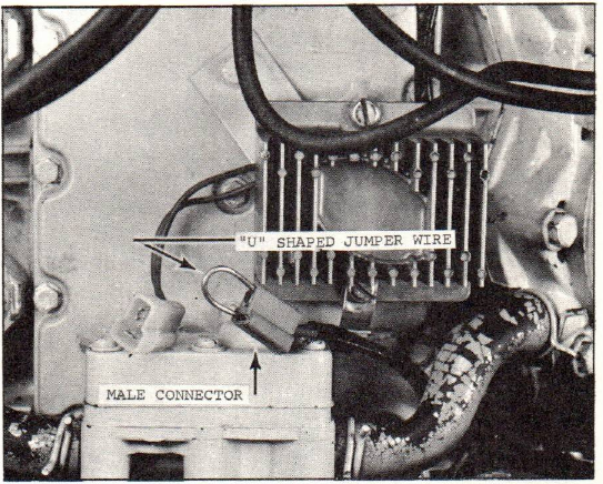
- Cut and bend a short 1-1/2" wire into a "U" shape, which is used as a jumper wire.
- Insert "U" shaped wire into "male" nylon connector, as shown in Figure 1.
- The voltage to the "on" light on the dash panel cannot be controlled, as we eliminate the transistor voltage regulator in making this test. As a precautionary measure, remove the "on" light bulb, as the uncontrollable voltage could burn it out.
- Start and run engine at 2000 to 2200 RPM - observe the ammeter on the dash panel while making this test.
- If the ammeter shows a full 20 amp charge, the alternator is functioning properly - see Figure 1.
- If the ammeter shows only a half charge (10 amp), one set of diodes are not working. Shut off the engine, disconnect the battery, and test both the positive and negative sets of diodes. Replace the defective set of diodes, reconnect the battery, restart the engine and repeat this test. The ammeter should now read 20 amps.
- If the ammeter shows no charge:
- The 60 amp fuse might be burned out.
- Both sets of diodes may not be working.
- The stator windings or other wires may be shorted or open.
- The ammeter might be defective.
Checking voltage output:
After completing the above tests satisfactorily, reconnect the regulator into the circuit.
As there is no bench test for the solid state regulator, it must be checked on the engine while the engine is operating. The battery should be fully charged and in good condition before making this test.
- Run the engine for 20 minutes to warm up the transistor voltage regulator.
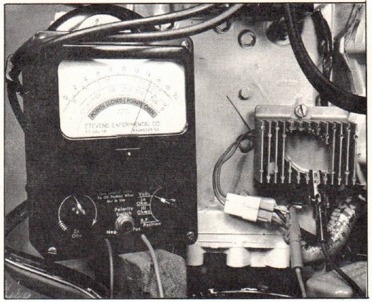
- Use a good quality, accurate voltmeter, with at least a 15-volt scale.
- Connect the positive voltmeter lead to the RED wire at the regulator harness connector. (See Figure 2)
- Connect the negative voltmeter lead to the regulator housing. (See Figure 2)
NOTE: (Do not connect the voltmeter across the battery, because the regulator is designed to compensate for the resistance contained within the wiring harness.)
- With the engine running at approximately 2,000 RPM, the voltmeter should read between 14.2 and 15.3 volts.
- If the regulator does not regulate between 14.4 and 15.0 volts, one of the following conditions exists:
- Regulates, but out of "spec" (see para. #5) - regulator is out of calibration and must be replaced.
- Voltmeter continues to read battery voltage -
- Poor or open connections within the wiring harness. - check wiring and repair.
- Regulator "open" - replace regulator.
- Voltage continues to rise.
- Regulator housing not grounded - check by connecting a jumper wire from the housing to the battery ground on the engine. If the regulator works with the jumper attached, check the ground connection between the regulator housing and the engine exhaust cover. (See SB-1091)
- Reversed wires in harness or plug will cause regulator to be permanently damaged. Connect wires per wiring diagram, and install a new regulator.
- Regulator shorted - replace regulator.
HERE IS WHAT TO LOOK FOR IN CASE OF FAILURES OF THE SOLID STATE VOLTAGE REGULATOR:
- Poor or loose connections ANYWHERE in the charging circuit.
- Poor ground between regulator housing and engine exhaust cover. (See SB-1091)
- Shorted alternator winding.
- Bare or frayed wires.
- Excessive temperatures.
- Grounded RED/BLACK stripe wire - (This will cause instantaneous regulator failure).
- Disconnecting the regulator with the circuit energized.
- Running the engine with the battery disconnected.
JOHNSON MOTORS
N. Peter Hansen
Administrative Assistant
NPH:rs
NOTE: Post on your V4-75 HP, V4-80 HP, VM-90 HP, and VM-100 HP Indexes under the heading "Electrical". Destroy SB-#1040 dated February 3, 1965.
Historical references
SB-1091 - referenced for checking the regulator ground connection. This revision directs dealers to destroy the earlier SB-1040 dated February 3, 1965.
Related bulletin: Original SB-1040