Johnson Service Bulletin SB-1160 - Ignition Mis-Fire
April 1968. Johnson describes an improved breaker-point assembly and a field-made indexing tool for accurately setting the breaker points on 1968 55, 65 and 85 H.P. capacitor-discharge ignition outboards.

April, 1968
SUBJECT: IGNITION MIS-FIRE
ON MODELS: TR(L)-10, 55 H.P.
VX, VXH(L)-14, 65 H.P.
V4S, V4A(L)-20, 85 H.P.
Since the first produced 1968 models using the breaker point C.D. ignition, several changes and Quality Control checks have transpired relative to the breaker points. As a result, #382484 Breaker Point assembly has been obsoleted and an improved assembly released under P/N 383655.
Inability to maintain proper point gap, a basic source of ignition mis-fire, was mainly due to the loose fitting fibre rocker arm on the pivot post. The addition of an Oilite bushing in the rocker arm and maintaining the correct diameter of the pivot post, has resulted in a set of points which can be installed and adjusted to maintain proper gap. The improved #383655 Breaker Assemblies are currently available thru your regular parts source.
Breaker point adjustment on the listed models is an operation which needs to be done most carefully. Setting the points at the specified gap with a feeler gauge has been the recommendation heretofore for these models. However, adjustment in this manner will often vary from person to person and we feel the best adjustment is obtained with the aid of a continuity light or ohmmeter.
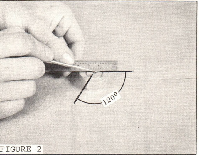
Since there are no timing fixtures available for these models and the relationship of flywheel timing marks do not necessarily correspond to point setting, it was necessary to develop another means. Mathematically, 1/3 of a revolution of the point adjusting screw (which has a 1/4-28 thread) is equivalent to .012" of movement. The only problem then is how to gauge 1/3 of a turn and the manner in which to proceed.
A simple tool for gauging 1/3 of a revolution (120°) can be made from already available parts as listed below:
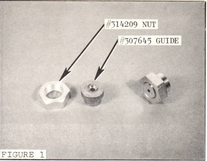
1 - 307645 Guide (This is a part of the Universal Flywheel Puller Adaptor Kit)
1 - 1/8" Allen Wrench
The 307645 Guide is a tight press fit in the flywheel nut. We chose using a hex nut as it has "built in" increment of 60°. After pressing the guide into the nut, use a #28 or 9/64" drill and bore thru
JOHNSON MOTORS, DIVISION OF OUTBOARD MARINE CORPORATION, WAUKEGAN, ILLINOIS 60085
the guide using the already present pilot hole for centering (Figure 1).
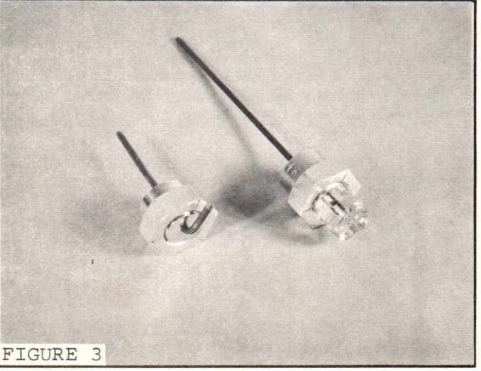
Next, lay a straight edge across the assembly as shown and make three scribe marks indicating 120° arcs (Figure 2). A regular "L" shaped 1/8" Allen Wrench can now be inserted to complete the tool. An alternate to a regular Allen wrench is the special item shown in Figure 3. This tool affords better access and is easier to use than a regular Allen wrench. It is available thru Wm. R. Simon, 1015 Fulton Avenue, Winthrop Harbor, Illinois. Remit $.60 with your order to cover postage paid shipment.
The following procedure for setting points is presently being used on our production line and is recommended for field service.
A. Remove flywheel, stator, distributor cap, wave washer and rotor.
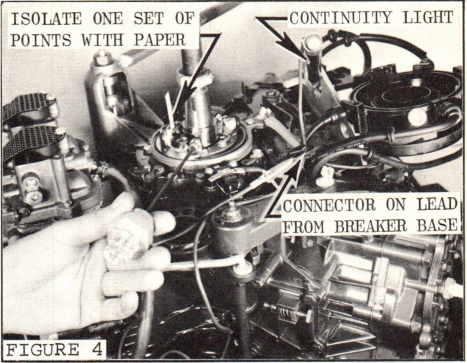
B. Disconnect the breaker point lead at the connector and connect an ohmmeter or continuity light to the breaker point side.
C. Isolate one set of breakers with a piece of paper or light cardboard while setting the other set.
D. Rotate the crankshaft so the rubbing block of the set of breakers you are setting is positioned on the high part of the cam. Be sure the anti-reverse running spring is not in contact with the shorting block.
E. Close this set of breakers to the precise point of contact as indicated by the ohmmeter or continuity light. Be
JOHNSON MOTORS, DIVISION OF OUTBOARD MARINE CORPORATION, WAUKEGAN, ILLINOIS 60085
careful with this setting as lateral force on the Allen wrench will give you a false setting (Figure 4).
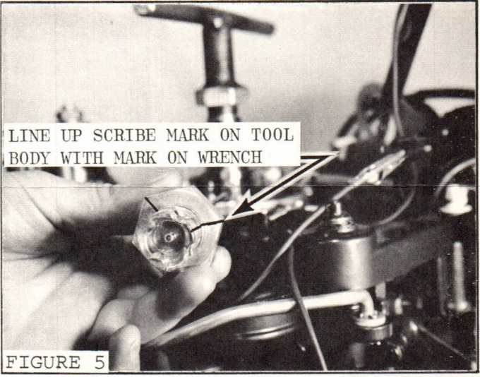
F. Using the tool previously described, line up one scribe mark on the body with the Allen wrench or a mark on the handle of the alternate tool mentioned earlier (Figure 5).
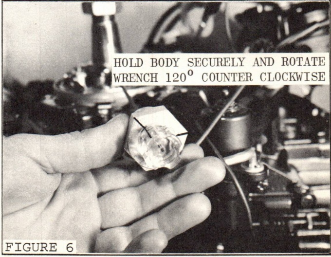
G. Holding the body secure, rotate the Allen wrench counter clockwise 120° (the next scribe mark) (Figure 6).
H. Repeat steps C thru G for the other set of breakers.
I. Reassemble the rotor, wave washer, stator, and flywheel.
J. Tank test motor and adjust the full advance stop screw to obtain proper full advance timing.
K. Readjust carburetor linkage as required and described in SB-#1149 and the Service Manual.
Carl Klawonn
Administrative Assistant
NOTE: Post on your VX-60 H.P. & V4-80 H.P. Indexes under the heading "Ignition".
SPECIAL NOTE: OMC Type "D" lubricant is available through your Parts Distributor under P/N 172121 in 1/2 oz. tubes. This is Shell Alvania EP-#2 lubricant required on the anti-reverse running springs on 1968, 55 - 100 H.P. motors.
Historical parts and service references
Breaker point assembly 382484 was replaced by improved assembly 383655. The field-made 120° adjustment tool uses flywheel nut 314209, guide 307645, and a 1/8-inch Allen wrench. The bulletin also identifies OMC Type D lubricant 172121.
Related bulletin: SB-1149 - Carburetor linkage adjustment, cited in step K of the factory instructions.