Issued December 1975, this Johnson Service Bulletin describes the 1976 35 H.P. cooling-system modification program, affected serial-number ranges, and installation instructions for cooling system kits 388147 and 388148. The factory bulletin and two-page instruction sheet is reproduced below with searchable instructions and six original technical illustrations, with Figure 6 displayed separately for legibility.
SB-#1397
December, 1975
SUBJECT: Cooling System Modification Program
ON MODELS: 1976 35 H.P.
NOTE
This service bulletin is to advise you of a cooling system modification program we have instituted on some 1976 35 h.p. motors. If you had purchased any of the motors involved, you would have been notified by certified mail prior to receiving this bulletin.
Please read the attached dealer letter and instruction sheet which explains in detail the problem and the corrective action being undertaken.
All 1976 models built after the following serial numbers will have the cooling system improvements. In addition, many engines with serial numbers lower than those listed below were modified before shipment. Engines which have the cooling system improvements will have the letters "GCOK" on the motor carton near the serial number.
MODEL NUMBER
SERIAL NUMBER
35R76S
4455946
35RL76S
4457803
35E76S
4459803
35EL76S
4462976
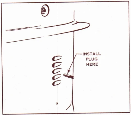
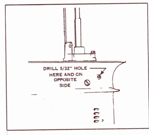
If you have a 35 h.p. engine in your shop for service and the serial number is lower than those listed above, inspect the gearcase to see if the cooling system improvements have been made. (Refer to Figures 1 and 2 on attached instruction for location of plug and drilled holes which indicate gearcase has been modified.) If engine has not been modified, contact the Johnson Outboards Service Department, Desk J372, 312/689-6293 for parts necessary to improve the cooling system.
JOHNSON OUTBOARDS
D. J. Leinonen Technical Data Coordinator
NOTE: Post on your 35 h.p. index under heading "Lower Unit."
INSTRUCTION SHEET FOR 388147 & 388148 COOLING SYSTEM KITS MODELS 35R76, 35RL76, 35E76, 35EL76
1.Remove gearcase. Remove plastic driveshaft spacer from exhaust housing. (Spacer may come off on driveshaft when gearcase is removed.) Remove and set aside water tube.
2.Apply Permatex No. 2 to plug supplied and install into drain hole in gearcase. See Figure 1. Plug is installed smooth diameter first. Use a hammer to drive plug flush with gearcase surface.
FIGURE 1
3.Drill a 5/32" diameter hole in forward half of circular locating boss just forward of vent plug. See Figure 2. Repeat operation on opposite side of gearcase. Remove metal chips from inside gearcase.
FIGURE 2
4.Remove impeller housing, impeller and impeller plate.
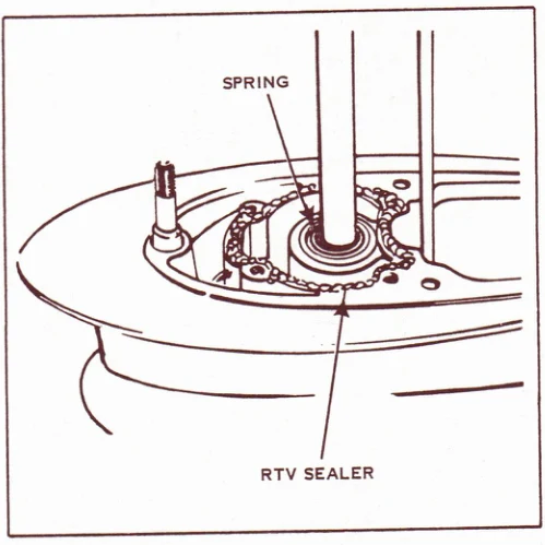
5.Visually inspect driveshaft seal in gearcase to make sure spring is in place on seal. See Figure 3.
FIGURE 3
6.Clean gearcase flange and impeller plate of any old adhesives.
7.Apply a thin bead of RTV silastic sealer to gearcase where impeller plate will be mounted. See Figure 3. RTV is available from your parts distributor under part number 263753 (black) and 262171 (white). RTV is also sold through local hardware stores as General Electric silicone bathtub caulk.
8.Install impeller plate, new impeller supplied, and impeller housing. Torque impeller housing screws to 5 - 7 foot pounds.
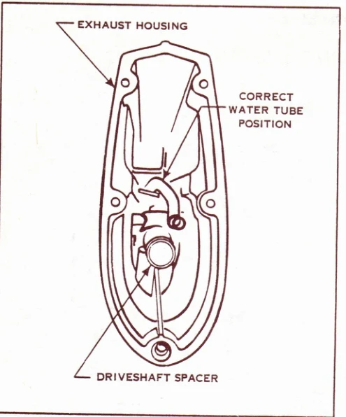
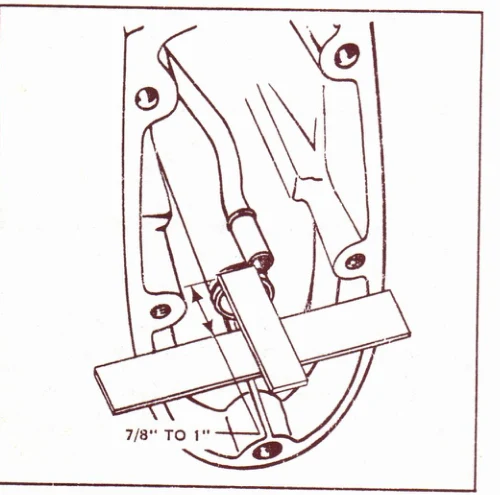
9.Insert new water tube (P/N 322077 std. or 322078 long) into upper grommet in exhaust housing. Assembly will be eased by first lubricating end of water tube with liquid hand soap. Water tube should be positioned as shown. See Figure 4. When properly installed, end of tube will be approximately 7/8" to 1" above mounting flange of exhaust housing. See Figure 5.
FIGURE 4
FIGURE 5
10.Apply Permatex No. 2 to upper o-ring on driveshaft spacer. Install spacer in exhaust housing.
11.Lubricate impeller housing grommet with liquid hand soap. Lubricate upper driveshaft spline with OMC Sea-Lube Multi-purpose grease.
12.Re-install gearcase making sure water tube starts into impeller housing grommet, shift rod is in connector and driveshaft spacer is in pump housing.
13.Torque gearcase screws to 5 - 7 foot pounds and nut on gearcase stud to 10 - 12 foot pounds.
14.Install shift rod connector screw and torque to 24 - 36 inch pounds.
15.Check for proper shifter adjustment as follows:
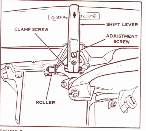
a.Place gearshift in neutral. Propeller should turn freely. The roller on the shift lever should be centered on the neutral detent of the shifter lock lever. When shifted into forward gear, you should feel a slight shifter dog drag when rocking propeller shaft back and forth between lugs of shifter dog.
b.If out of adjustment, shift gearcase linkage into neutral. Loosen shift lever clamp screw and adjustment screw. See Figure 6. Pull shift lever slightly toward reverse and re-tighten screws.
c.When in neutral, propeller shaft should turn freely. Shift into forward and check for drag as in (a) above. Repeat step (b) if necessary. This drag in forward gear assures that shifter dog and gear are in full engagement.
16.Run engine in test tank. Check water discharge at exhaust relief hole to determine if engine has adequate water flow for cooling.
17.Tag and set aside old water tube & impeller. Hold these parts for pickup by area service representative.
Source note: The uploaded three-page document includes the service bulletin and two pages of installation instructions. It refers to a separate dealer letter, which was not included in the supplied PDF.