Johnson Service Bulletin SB-996 - Timing and Synchronizing, 90 H.P.
Illustration note: Original SB-996 image files were missing from the archive. Figures 1, 2, 5, 6 and 7 are shown from the later SB-996 Rev. 1. Figures 3 and 4 are shown together with the factory handwritten cancellation directing readers to SB-996A. Consult the revised procedure before servicing.
Issued December 2, 1963, this Johnson Motors bulletin explains distributor timing and carburetor synchronization on the 90 H.P. V4M(L)-10S engine. The original three-page factory bulletin and seven instructional photographs are reproduced below.
SB-#996 File after SB-#995
December 2, 1963
SUBJECT: TIMING AND SYNCHRONIZING - 90 HP - MODEL V4M(L)-10S
Timing and synchronizing procedures for the 90 H.P. engine are similar to those used on previous 75 HP models. Flywheel timing marks have been relocated for ease of alignment.
Timing - To be sure distributor is properly timed with the crankshaft, proceed as follows:
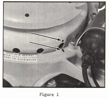
Step 1 - Align the punch mark (painted red) on the flywheel with the arrow on the ring gear guard marked "belt timing" (figure 1).
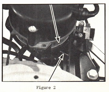
Step 2 - Notch in distributor drive pulley rim should be aligned with timing line on distributor bracket (figure 2).
If mark and notch do not line up, loosen distributor bracket screws (3) and reset drive pulley. Place tension on belt and retighten screws. Correct belt tension will allow a deflection of 5/16 to 3/8 inch with a 1 lb. load near the center of the belt.
Figure 1Figure 2
PAGE 2 SERVICE BULLETIN #SB-996JOHNSON MOTORS, DIVISION OF OUTBOARD MARINE CORPORATION, WAUKEGAN, ILLINOIS 60086
Synchronizing - Proceed as follows to synchronize the distributor with the carburetor.
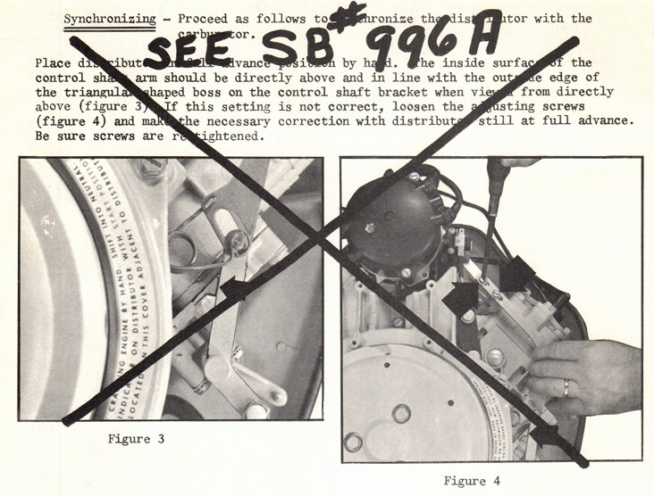
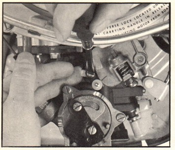
Place distributor in full advance position by hand. The inside surface of the control shaft arm should be directly above and in line with the outside edge of the triangular shaped boss on the control shaft bracket when viewed from directly above (figure 3). If this setting is not correct, loosen the adjusting screws (figure 4) and make the necessary correction with distributor still at full advance. Be sure screws are re-tightened.
Figures 3 and 4 (annotated in later revision; see SB-996A)
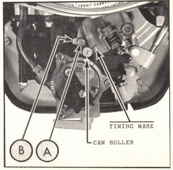
Step 3 - Check the pickup position of the throttle with the cam. The roller should begin to open the throttle as the center of the roller shaft aligns with the mark on the cam (Figure 5). If this adjustment is incorrect, loosen screw "A". Push throttle arm "B" toward cam (figure 6) and while holding roller in contact with throttle cam, re-tighten screw "A". Center of roller shaft must be in alignment with cam timing mark during this adjustment.
Re-check adjustment.
Figure 5
PAGE 3 SERVICE BULLETIN #SB-996JOHNSON MOTORS, DIVISION OF OUTBOARD MARINE CORPORATION, WAUKEGAN, ILLINOIS 60086
Figure 6Figure 7
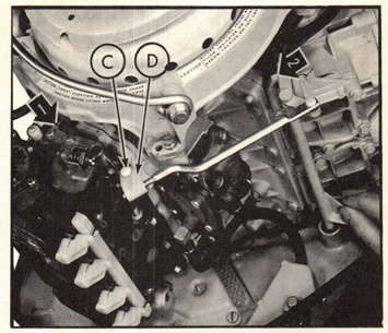
Step 4 - Move throttle control shaft to full throttle position. The control shaft arm should be against its stop on the control shaft bracket, (arrow 2, figure 7) and throttle arm "B" should be against its stop on the carburetor casting (arrow 1, figure 7). If either of these are not against their respective stops, remove pin "C" (figure 7) and adjust throttle control rod clevis "D" until these settings are possible. Replace pin, washers and cotter pin.
JOHNSON MOTORS
Robert Compton Administrative Assistant
RC:eb
NOTE: Post on your V4-90 HP Index under the heading "IGNITION".
Historical references
Factory filing instruction: File after SB-995. This bulletin applies to the 90 H.P. V4M(L)-10S engine. Figures 1 through 7 are preserved above and can be linked individually.