Johnson SB-996A - Revised Synchronizing Procedure for V4M 90 HP Engines
February 1965. Supplement to SB-996 with revised distributor and carburetor synchronization procedure for V4M 90 HP engines.
Related factory bulletin: SB-996 Rev. 1.

SB-#996A
Supplement to
SB-#996
February, 1965
SUBJECT: REVISED SYNCHRONIZING PROCEDURE FOR V4M-90 HP ENGINES.
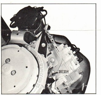
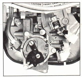
Fig 1
Fig 2
To improve acceleration and mid-range smoothness of operation, the follow-
ing revised synchronization procedure has been established for the subject
engines:
Refer to SB-996 - page 1, steps #1 and #2. Check timing and make correc-
tions if necessary.
Proceed to page 2, SB-996. Disregard synchronizing procedure as outlined
and shown, figures #3 and #4.
New procedure for synchronizing distributor with carburetor is as follows:
Disconnect the remote control cable from engine. Place distributor in full
advance position by hand. The outside of the control shaft arm should be
directly in line with the outside edge of the triangular shaped boss on
the control shaft bracket when viewed from above (figure 1). To obtain
this setting, loosen the adjusting screws (figure 1) and make the neces-
sary correction with the distributor held at full advance position.
On some engines there may be insufficient adjustment to obtain this set-
ting; on these engines adjust the distributor link to its shortest length,
which will be very close to the setting recommended above.
(over)
PAGE 2 SERVICE BULLETIN
JOHNSON MOTORS, DIVISION OF OUTBOARD MARINE CORPORATION, WAUKEGAN, ILLINOIS 60086
After this adjustment has been made and the adjusting screws retightened,
move the throttle lever to idle position. It will be necessary to re-
adjust the idle stop screw (figure 2) so that the engine idles at 600-
650 RPM in gear. In idle position, check to be sure that the throttle
cam roller is a minimum of 1/16" clear of the throttle cam (figure 2).
Move the throttle lever to full throttle
position and check to see that the dis-
tributor is fully advanced. It may be
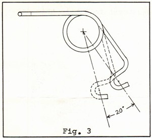
necessary to remove spring #307354 at the
top of the control shaft (figure 1) and
increase its tension slightly. (See Fi-
gure #3 for recommended amount of reform-
ing.) Move the distributor back and forth
to be sure that the various attached wires
are not restricting distributor travel.
The lower high tension lead retainer
#310446 may be removed or re-located if
it causes the leads to restrict the dis-
tributor movement.
Proceed with steps #3 and #4 of SB-996.
Re-attach remote control cable to engine. It will be necessary to re-
adjust cable trunion in order that attachment be made to control shaft
lever pin.
What actually is being accomplished by this new procedure is simply that
we are opening the throttle valves sooner in relation to ignition ad-
vance. This allows the engine to commence taking in a greater volume
of air through the carburetor at a lower RPM. By so doing, better
scavenging of exhaust gases from the combustion chambers will take
place and there will be less tendency toward loading. The end result
is a much smoother running engine through and in mid-range operation.
Another valuable side effect is that the engine will, each time, re-
turn to a more consistent idling speed (600-650 RPM in gear). Also,
trunion adjustment will fall midway in the threaded area on the con-
trol cable.
JOHNSON MOTORS
Jack Penland
Service Promotion Manager
JP:rs